Liquid ejection apparatus

Active Publication Date: 2013-04-04
BROTHER KOGYO KK
View PDF6 Cites 4 Cited by
  • Summary
  • Abstract
  • Description
  • Claims
  • Application Information

AI Technical Summary

Benefits of technology

[0006]When the time interval between image formation on one page and that on another page is relatively short, the recording process is executed with respect to many recording media in a short time. In this case, the liquid is frequently ejected from the head. Therefore, the viscosity of the liquid hardly increases, and it is less likely that the recording quality is deteriorated. If, despite this fact, ejection performance is recovered based on the number of copies or the printing intervals without variation, the process of recovering the ejection performance may be executed once a pre-set number of copies or printing interval has been reached, even though the recording quality, has not yet been significantly deteriorated. This could he a waste of the liquid or the power.
[0007]In view of the above problem, an object of the present invention is to provide a liquid ejection apparatus capable of executing the process of recovering, the ejection performance suitably based on the time interval between one image formation and another image formation.
[0008]A liquid ejection apparatus, includes a liquid ejection, a conveyor, a according controller, and a flashing controller. The liquid ejection head ejects a liquid. The conveyor conveys one or more recording media along a conveyance path. The recording controller causes the conveyor to convey the recording media, and executes control for ejecting the liquid from the liquid ejection head so that an image is formed on the recording media based on image data. The flashing controller executes flashing control for causing the conveyor to temporarily stop conveyance of the recording media, and for causing liquid ejection from the liquid ejection head, based on drive data which is not related to image formation. The flashing controller determines timing for executing a subsequent flashin

Problems solved by technology

This could he a waste of

Method used


Image

  • Liquid ejection apparatus
  • Liquid ejection apparatus
  • Liquid ejection apparatus

Examples


first embodiment

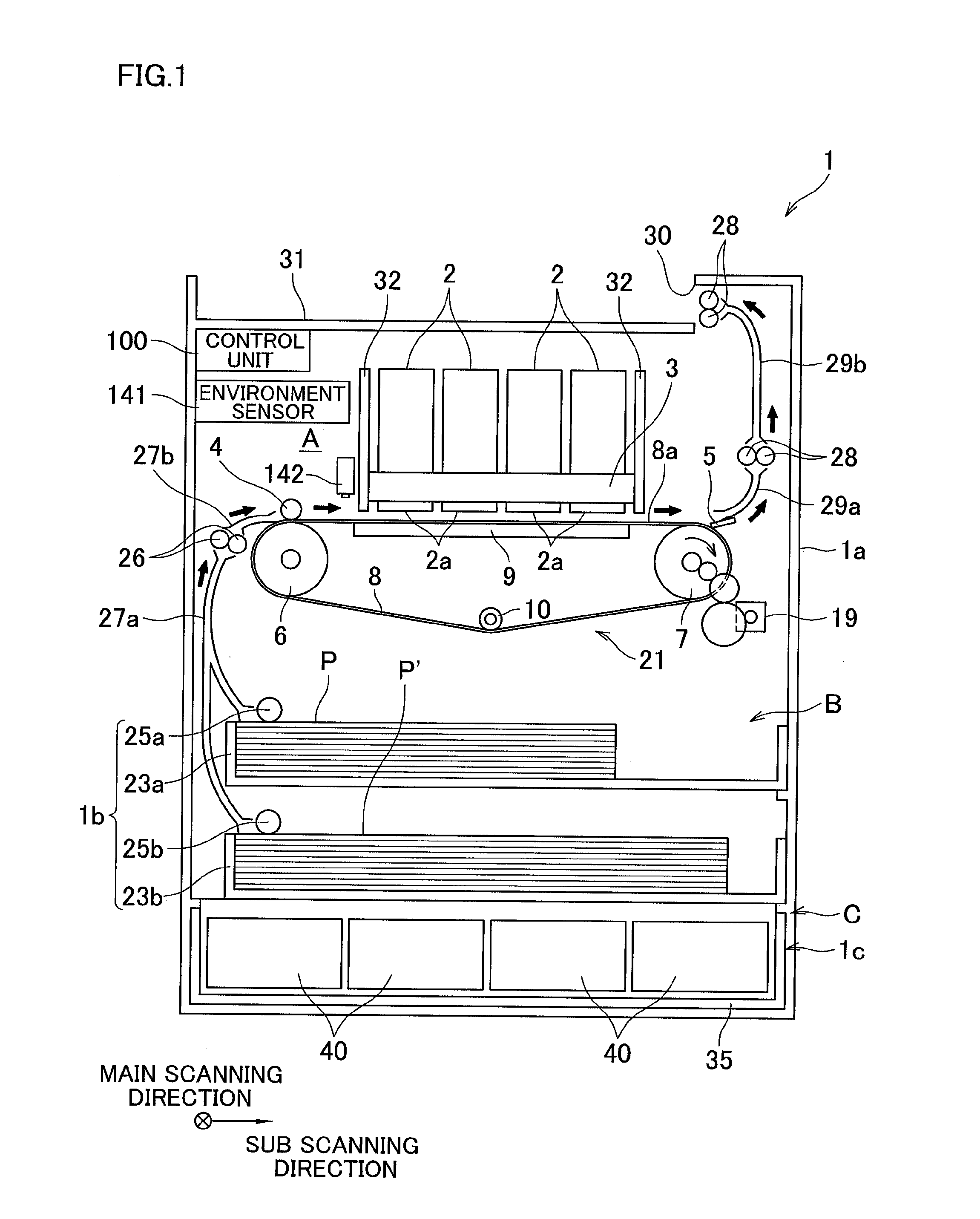
[0025]First, the following describes an overall structure of an ink-jet printer 1 related to the present invention, with reference to FIG. 1 and FIG. 2.

[0026]The printer 1 has a casing 1a having a rectangular parallelepiped shape. At an upper portion of the casing 1a is provided a sheet output unit 31. In the following description, the inside space of the casing 1a is parted into space A, B, and C in this order from the top. The spaces A and B have a conveyance path connecting to the sheet output unit 31. In the space A, conveyance of a sheet P or P′, and image recording on the sheet P or P′ take place. In the space B, an operation related to sheet feeding takes place. In space C are accommodated ink cartridges 40 each serving as an ink supply source.

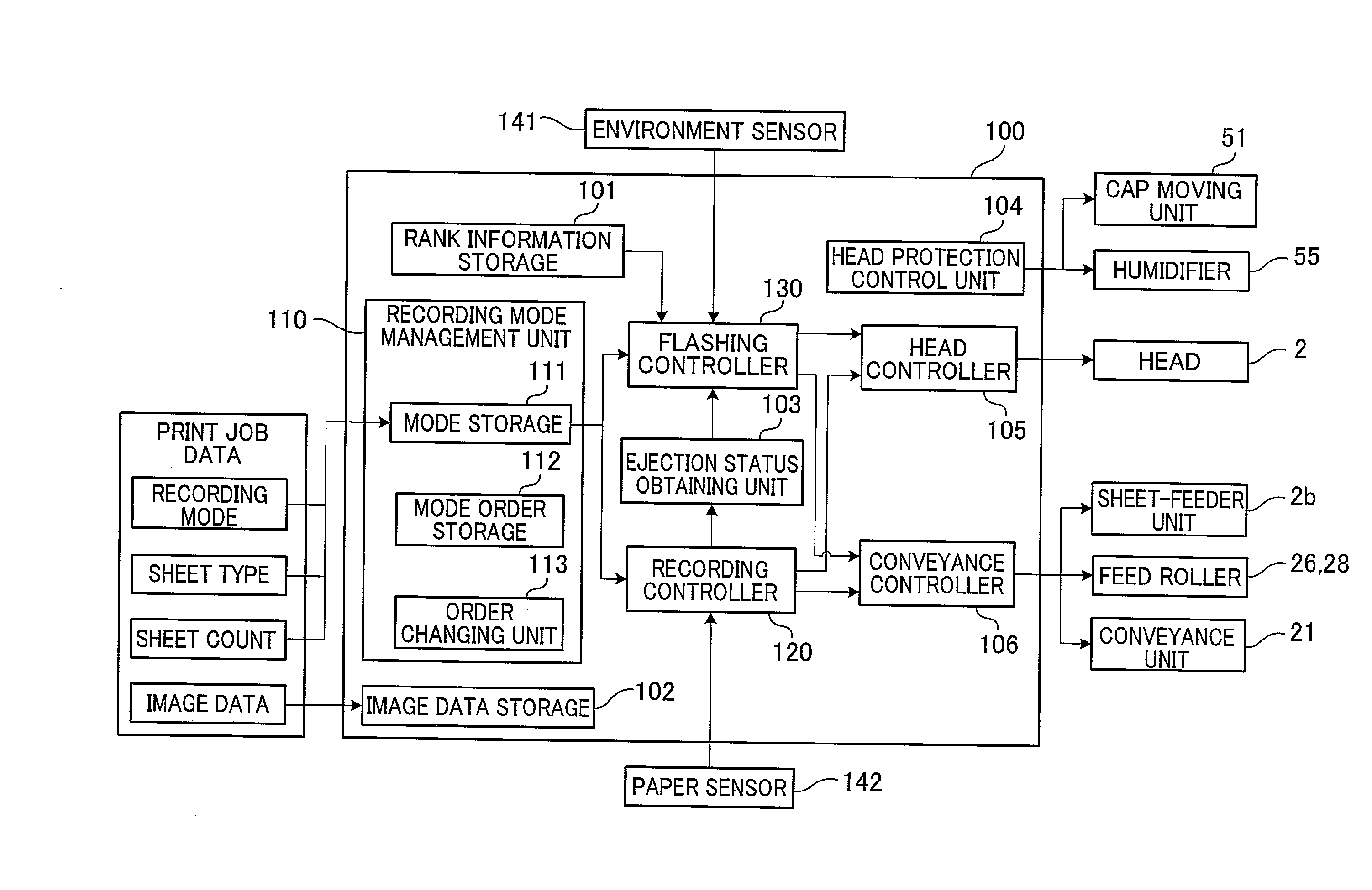
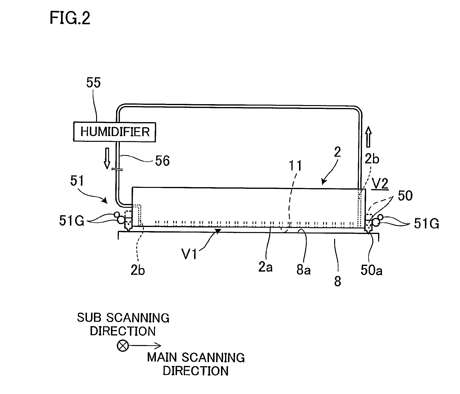
[0027]In the space A are disposed four ink-jet heads 2 (hereinafter, heads 2), cap units 50 which cover the ejection faces 2a of the heads 2 respectively, a conveyance unit 21 which conveys the sheet P or P′, a guide unit which guides t...

second embodiment

[0093]With the second embodiment, the flashing operation is executed based on they interval which is obtained based on the detection result of the paper sensor 142. Further, the coefficient is set based on the type of sheet so that, for example the time interval before the flashing operation is longer with an increase in the length of the sheet and with an increase in the number of ink ejections. Therefore, unnecessary flashing operation is suitably avoided for the length of the sheet, while appropriately ensuring the necessary flashing operation.

[0094]The following describes a third embodiment of the present invention, with reference to FIG. 11. The following description mainly deals with the difference from the first embodiment and the second embodiment, and omits the description for the other structures. The third embodiment is intended, for a case of using a rolled paper P′ which is continuous relative to the sheet conveyance direction, instead of the sheet P or the sheet P′ whi...


PUM


Abstract

A liquid ejection apparatus includes a liquid ejection head, a conveyor, a recording controller, and a flashing controller. The conveyor conveys a recording medium along a conveyance path. The recording controller causes the conveyor to convey a recording medium, and controls liquid ejection from the liquid ejection head to form an image on the recording medium based on image data. The flashing controller causes the conveyor to temporarily stop conveyance of the recording medium, and causes liquid injection from the liquid ejection head based on drive data which is unrelated to image formation. The flashing controller determines timing for executing a subsequent flashing control on that, within a print enforceable period between one flashing control and the subsequent flashing control, the number of pages subjected to image formation based on image data increases with a decrease in time interval between image formation on one page and on another page.

Description

CROSS-REFERENCE TO RELATED APPLICATION[0001]The present application claims priority from Japanese Patent Application No. 2011-215852, which was filed on Sep. 30, 2011 the disclosure of which is herein incorporated by reference in its entirety,BACKGROUND OF THE INVENTION[0002]1. Field of the Invention[0003]The present invention relates to a liquid ejection apparatus having a liquid ejection head.[0004]2. Description of the Related Art[0005]When a recording process is executed continuously to a recording medium, the viscosity of a liquid in the liquid ejection head increases, which may cause deterioration in the recording quality. To prevent deterioration of the recording quality, there is pre-ejection which eject the liquid from the liquid ejection head before executing a recording process. There has been a traditional technology which pre-ejection of a larger ejection amount than ordinary pre- ejection is selected based on a determining condition such as the number of copies, the pr...

Claims


Application Information

Patent Timeline
IPC IPC(8): B41J29/38
CPCB41J2/1652B41J2/165
Inventor ITO, YUICHI
Owner BROTHER KOGYO KK
Why Eureka
Try Eureka