Projector and method for controlling projector

a projector and projector technology, applied in the direction of projectors, color television details, instruments, etc., can solve the problems that the correction cannot be made by using the projector alone, and cannot solve the problem, and achieve the effect of simple operation

Active Publication Date: 2013-04-04
SEIKO EPSON CORP
View PDF3 Cites 25 Cited by
  • Summary
  • Abstract
  • Description
  • Claims
  • Application Information

AI Technical Summary

Benefits of technology

[0007]An advantage of some aspects of the invention is to provide a projector that allows a user to geometrically correct a projected image (correct the shape of a projected image) by using the projector alone based on simple operation and a method for controlling the projector.

Problems solved by technology

The correction cannot therefore be made by using the projector alone.
Since pincushion distortion cannot be corrected only by moving the corners of the projected image, the configuration of the related art described above cannot solve the problem.

Method used


Image

  • Projector and method for controlling projector
  • Projector and method for controlling projector
  • Projector and method for controlling projector

Examples


first embodiment

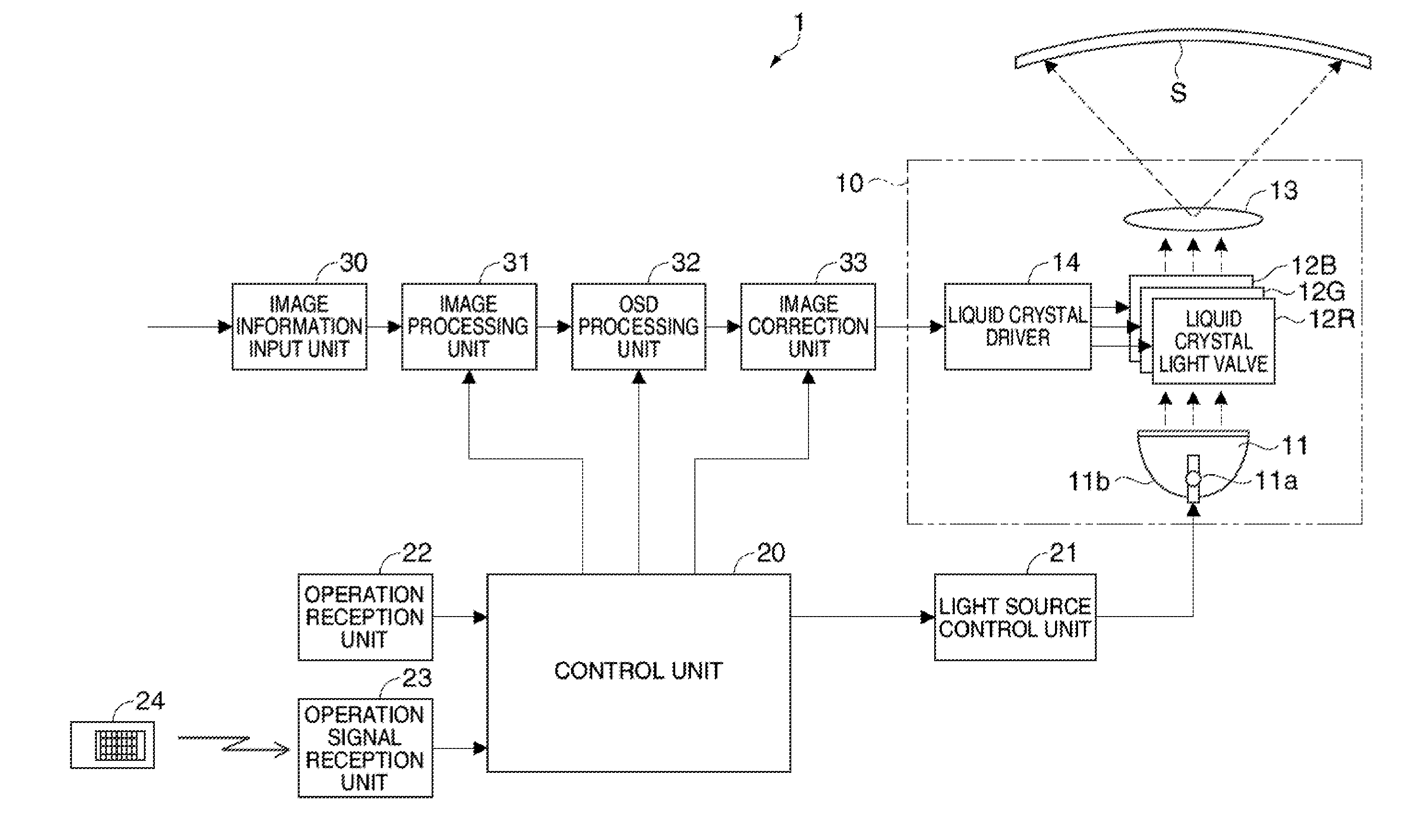
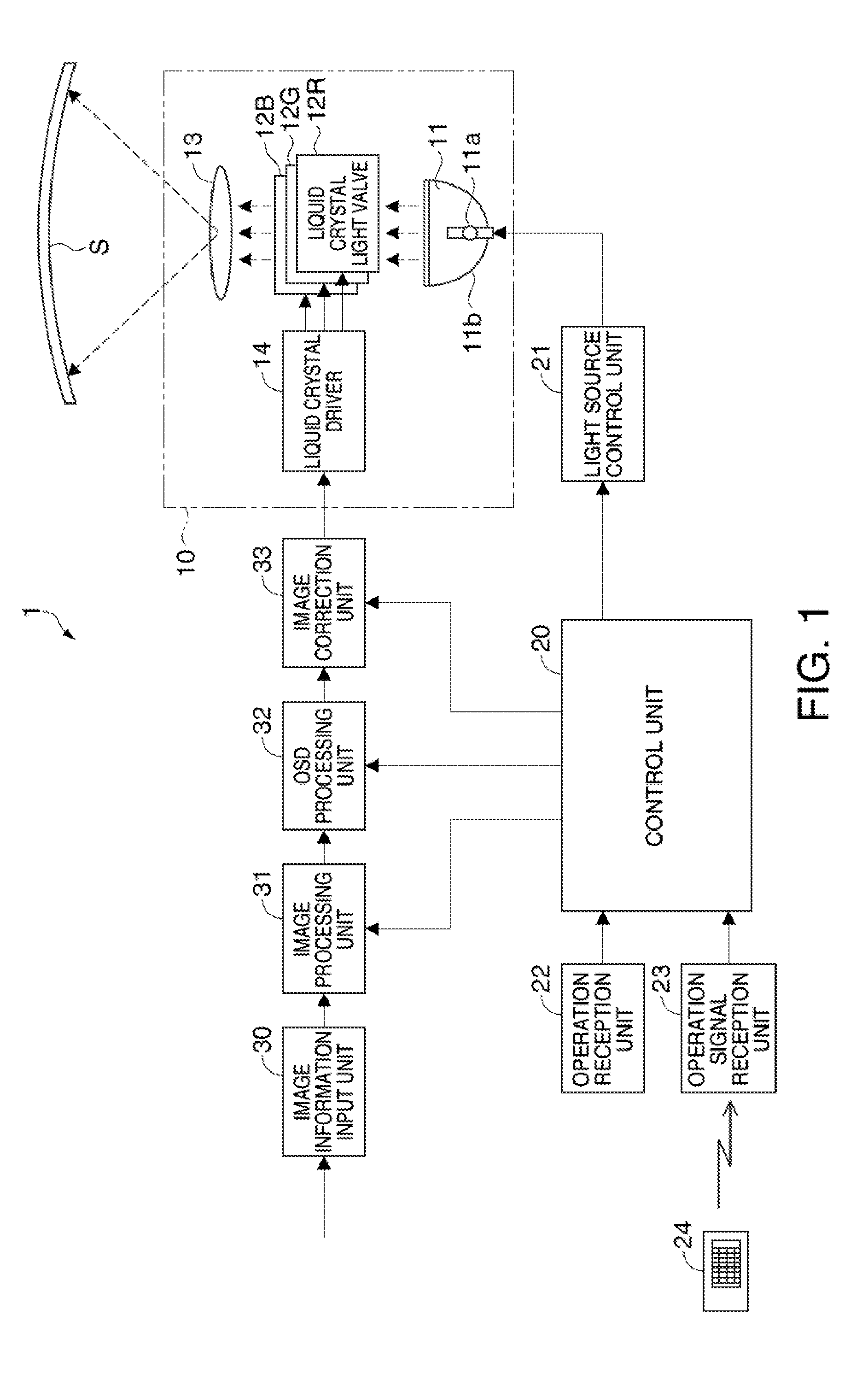
[0065]FIG. 1 is a block diagram showing a schematic configuration of a projector according to a first embodiment. The internal configuration of the projector will be described with reference to FIG. 1.

[0066]A projector 1 includes an image projection unit 10, a control unit 20, a light source control unit 21, an operation reception unit 22, an operation signal reception unit 23, a remote control 24, an image information input unit 30, an image processing unit 31, an OSD processing unit 32, and an image correction unit 33, as shown in FIG. 1.

[0067]The image projection unit 10 includes a light source apparatus 11 as a light source, three liquid crystal light valves 12R, 12G, and 12B as light modulators, a projection lens 13 as a projection system, and a liquid crystal driver 14. In the image projection unit 10, the liquid crystal light valves 12R, 12G, and 12B modulate light outputted from the light source apparatus 11 into image light, and the projection lens 13 projects and displays ...

second embodiment

[0120]A second embodiment to which the invention is applied will next be described. In the second embodiment, trapezoidal distortion of an image projected on the projection surface S and distortion called pincushion distortion, barrel distortion, or otherwise named are corrected.

[0121]FIG. 7 is a block diagram showing a schematic configuration of a projector 2 according to the second embodiment.

[0122]The projector 2 shown in FIG. 7 includes an image projection unit 10, a control unit 20, a storage unit 41, an input operation unit 42, an image information input unit 30, an image processing unit 31, an OSD processing unit 32, and an image correction unit 33. In the second embodiment, components common to those in the first embodiment have the same names and reference characters, and no description thereof will therefore be made.

[0123]In the image projection unit 10, which corresponds to a display unit according to the invention, light outputted from the light source apparatus 11 is mo...


PUM


Abstract

A projector that projects an image allows selection of one of a plurality of controlled objects located in correspondence with the vertices of the contour of the image and the sides of the contour, moves the selected controlled object within the image based on input operation, and corrects the contour of the image based on the moved controlled object.

Description

BACKGROUND[0001]The entire disclosure of Japanese Patent Application Nos. 2011-216716, filed Sep. 30, 2011 and 2011-216327, filed Sep. 30, 2011 are expressly incorporated by reference herein.1. TECHNICAL FIELD[0002]The present invention relates to a projector and a method for controlling the projector.2. RELATED ART[0003]There has been a known method for projecting an image from a projector and geometrically correcting the projected image on a user interface screen of a computer. For example, there has been a known geometric correction interface using an auxiliary line (Japanese Patent No. 3,845,386), in which application software that runs on a computer virtually narrows the area of a user interface screen and displays the thus narrowed screen to provide a virtual correction area that allows a user to correct an auxiliary line that does not fall within the screen and perform auxiliary-line-based correction even when a display having resolution lower than the panel size of the proje...

Claims


Application Information

Patent Timeline
Patent Type & Authority Applications(United States)
IPC IPC(8): G03B21/14
CPCG03B21/006H04N9/3185G03B21/142G03B21/147H04N9/3194
Inventor YOSHIMURA, JUNKOBAYASHI, MAKOTO
Owner SEIKO EPSON CORP
Why Eureka
Try Eureka