Imaging system and method

a technology of imaging system and method, applied in the field of non-destructive testing, can solve the problems of low contrast, low quality imaging with low resolution, and wide main lobe and side lobe,

Inactive Publication Date: 2013-04-04
GE INSPECTION TECH LP
View PDF5 Cites 33 Cited by
  • Summary
  • Abstract
  • Description
  • Claims
  • Application Information

AI Technical Summary

Problems solved by technology

With less elements in an array structure, it suffers from the inherent drawback of having a wide main lobe and higher level side lobes at predictable angles.
This produces lower quality imaging with low resolution caused by less focused response due to the wide main beam, and the low contrast between the true reflections and suffering from significant interference due to the high level unwanted side lobes.
The level of the side lobes can be suppressed by using different shading windows, however, this widens the main lobe as the trade off price which, further decreases imaging resolution.
Other methods have been considered for effectively reducing the effect of the side lobes, such as Minimum Variance method, but these generally involve a considerable level of calculation, resulting in increased costs and reduced speed.
Whilst the level of the side lobes can be reduced by using a larger array structure, this increases the cost, size and complexity of any such system.

Method used


Image

  • Imaging system and method
  • Imaging system and method
  • Imaging system and method

Examples


Embodiment Construction

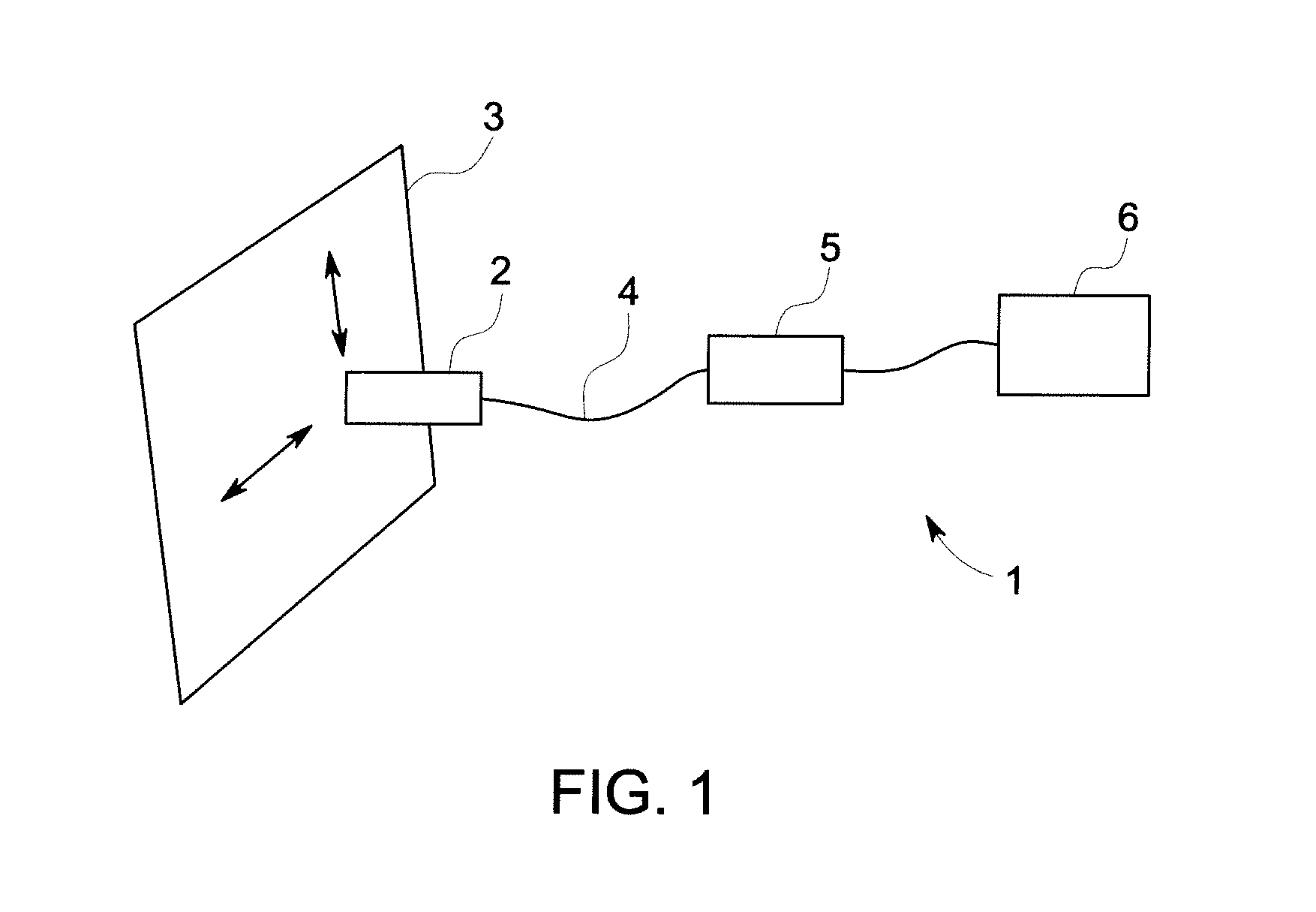
[0020]FIG. 1 shows an embodiment of an ultrasonic testing system 1. The system includes a probe 2 for sending and receiving signals to and from a test object 3. In an embodiment, the probe 2 is arranged to send and receive a reflected ultrasonic signal from the test object 3. However, in an embodiment, the probe 2 could instead be arranged to receive ultrasonic signals transmitted through a test object 3. The test object 3 could be any suitable object to be analysed for flaws and defects, such as, for example, panels of a vehicle such as an aircraft or a ship, sections of a pipeline or parts of an industrial plant which may take place without having to remove the object from surrounding structures. In use, the probe 2 is moved over to the surface of the test object 3 to analyse the structure of the test object 3. The probe 2 has an array of transducer elements. A probe cable 4 connects the probe 2 to an ultrasonic test unit 5. The ultrasonic test unit 5 has a control processor for s...


PUM


Abstract

A method of operating an ultrasound imaging system having an array of transducer elements. The method comprises transmitting a plurality of ultrasound signals, each transmission using a different sub-aperture of the array, receiving a plurality of reflected ultrasound signals by a receive array corresponding to each sub-aperture transmission, calculating a coherency factor corresponding to the proportion of coherent energy in the received signals from each sub-aperture transmission and weighting the received output by the calculated coherency factor, and synthesizing all weighted outputs under all different sub-aperture transmissions.

Description

BACKGROUND OF THE INVENTION[0001]Embodiments of the present invention relate generally to non-destructive testing and, more particularly, to ultrasound imaging.[0002]Non-destructive testing devices can be used to inspect test objects to identify and analyse flaws and defects in the objects. An operator is able to move a probe at or near the surface of the test object in order to perform testing of both the object surface and its underlying structure. Non-destructive testing can be particularly useful in some industries such as aerospace, power generation, oil and gas recovery and refining where object testing must take place without removal of the object from surrounding structures and where hidden defects can be located that would otherwise not be identifiable through visual inspection.[0003]One example of non-destructive testing is ultrasonic testing. When conducting ultrasonic testing, an ultrasonic pulse can be emitted from a probe and passed through a test object at the charact...

Claims


Application Information

Patent Timeline
Patent Type & Authority Applications(United States)
IPC IPC(8): G01S15/89
CPCG01S15/8927G01S7/52047G01N29/262G01N29/069G01S15/8997
Inventor QIAO, XIAOYUJOBST, MATTHIAS
Owner GE INSPECTION TECH LP
Why Eureka
Try Eureka