Antenna Driver Circuit for NFC Reader Applications

a driver circuit and reader technology, applied in the field of driver, can solve the problems of high current requirement, circuit being very inefficient, and not being able to track the changes in battery voltag

Active Publication Date: 2013-04-04
NXP USA INC
View PDF18 Cites 60 Cited by
  • Summary
  • Abstract
  • Description
  • Claims
  • Application Information

AI Technical Summary

Problems solved by technology

As such, to output a magnetic field at a given amount of power, the power amplifier 230 is required to output a higher amount of current due to the limitation in the driving voltage, which is inefficient given that a larger battery voltage of 5.5V is available.
In particular, the peak-to-peak voltage output by the power amplifier 230 remains constant at VLDOreg of about 2V and is not capable of tracking the changes in the battery voltage.
Therefore, due to the limitation in output voltage, in the conventional topology, a higher amount of current is required to output the magnetic field at the given amount of power.
The conventional topology does not allow for reduction in the overall current consumption of the circuit leading to the circuit being very inefficient.

Method used


Image

  • Antenna Driver Circuit for NFC Reader Applications
  • Antenna Driver Circuit for NFC Reader Applications
  • Antenna Driver Circuit for NFC Reader Applications

Examples


Embodiment Construction

[0019]In the following description, numerous specific details are set forth in order to provide a thorough understanding of the invention. However, it will be apparent to those skilled in the art that the invention, including structures, systems, and methods, may be practiced without these specific details. The description and representation herein are the common means used by those experienced or skilled in the art to most effectively convey the substance of their work to others skilled in the art. In other instances, well-known methods, procedures, components, and circuitry have not been described in detail to avoid unnecessarily obscuring aspects of the invention.

[0020]References in the specification to “one embodiment,”“an embodiment,”“an example embodiment,” etc., indicate that the embodiment described may include a particular feature, structure, or characteristic, but every embodiment may not necessarily include the particular feature, structure, or characteristic. Moreover, s...


PUM


Abstract

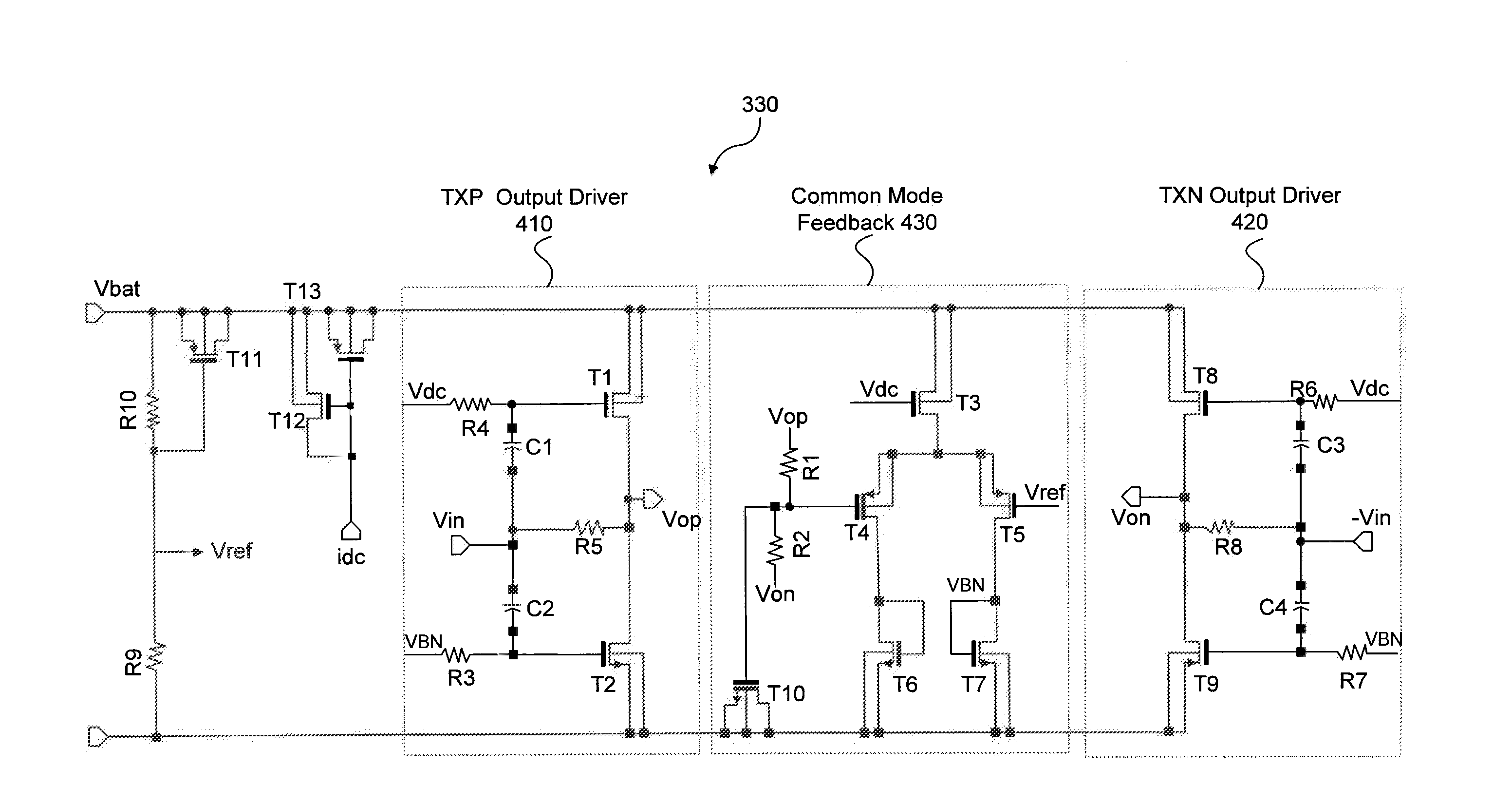
A power amplifier, supplied by a supply voltage, to drive an antenna to output a magnetic field, comprising a differential stage configured to output an output signal to drive the antenna, and a feedback stage configured to receive a common mode output voltage from the differential stage and to output a feedback voltage to regulate the output common mode signal to be proportional to the supply

Description

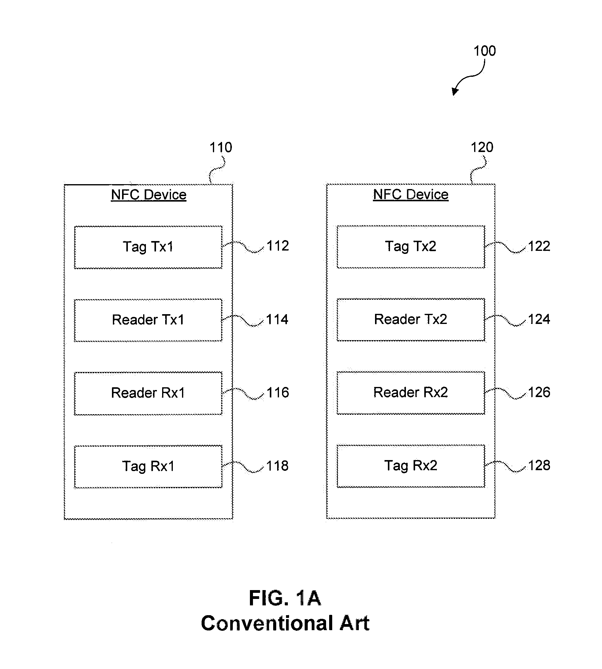
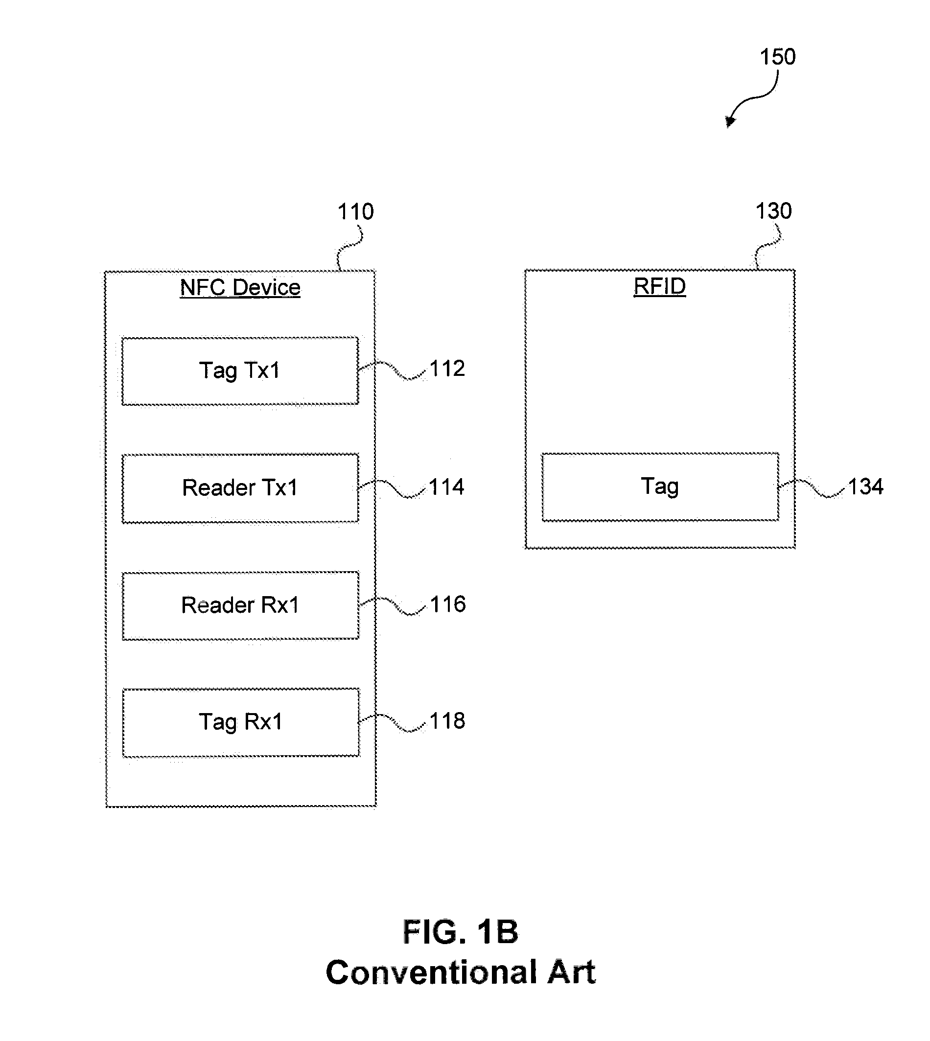
BACKGROUND OF THE INVENTION[0001]1. Field of the Invention[0002]The present invention relates to the design of an antenna driver used in a Reader Tx block of an NFC (near field communication) device. The antenna driver, which is part of the Reader Tx block, drives an antenna to output a magnetic field to establish communication with a Tag Tx block included in another NFC device.[0003]2. Background Art[0004]FIG. 1A shows a conventional communication system 100 including two NFC devices 110, 120 for communicating with each other. Each of the NFC devices 110, 120 includes a Tag Tx block 112, 122, a Reader Tx block 114, 124, a Reader Rx block 116, 126, and a Tag Rx block 118, 128 along with other supporting circuitry (not shown). The communication between the NFC devices 110, 120 is initiated when an antenna driver included in a Reader Tx block drives an antenna of one of the NFC devices to output a magnetic field that can power a Tag Rx and Tx-block included in the other NFC device. Th...

Claims


Application Information

Patent Timeline
Patent Type & Authority Applications(United States)
IPC IPC(8): H04B5/00H03F3/45
CPCH03F2203/45421H03F2200/411H03F3/45641H04B5/0075H03F3/245H03F3/45179H03F2203/45424
Inventor MARHOLEV, BOJKOSAFARIAN, AMINGHASEM
Owner NXP USA INC
Why Eureka
Try Eureka