Frictionless vertical suspension mechanism for prosthetic feet

a technology of vertical suspension and prosthetic feet, which is applied in the field of prosthetic devices, can solve the problems of relatively high energy consumption of prosthetic feet with vertical suspension shock absorbers, relatively heavy and/or bulky shock absorbers, and not well suited for high active use, and achieves the effect of greater energy return and low energy loss

Active Publication Date: 2013-04-04
OSSUR HF
View PDF2 Cites 14 Cited by
  • Summary
  • Abstract
  • Description
  • Claims
  • Application Information

AI Technical Summary

Benefits of technology

[0008]In accordance with one embodiment, a lightweight, low energy loss, vertical suspension system for prosthetic feet is provided. The vertical suspension system enables rollover characteristics between heel strike and toe-off of a prosthetic foot that are fit for everyday use and at the same time encourage highly active users (e.g., in running) through its suspension, energy return and light weight. The substantially frictionless nature of the vertical suspension system results in substantially greater energy return than prior art alternative suspension systems. As a result, the vertical suspension system is well-suited for physically demanding activities such as running.

Problems solved by technology

However, such shock absorbing members tend to be relatively heavy and / or bulky.
A common problem observed in prosthetic feet aiming for high travel suspension is that when in mid-stance, the bodyweight is supported by both the toe and the heel, but at heel strike or toe-off the weight is only supported by the respective part of the prosthetic foot.
This can cause an “obstacle” like feeling in the mid-stance of the rollover of the foot.
Existing prosthetic feet with vertical suspension shock absorbers are also heavy with relatively high energy losses from, for example, the foot hitting the ground and friction within the suspension system, and are therefore arguably not well suited for high active use, such as running.
The substantially frictionless nature of the vertical suspension system results in substantially greater energy return than prior art alternative suspension systems.

Method used


Image

  • Frictionless vertical suspension mechanism for prosthetic feet
  • Frictionless vertical suspension mechanism for prosthetic feet
  • Frictionless vertical suspension mechanism for prosthetic feet

Examples


Embodiment Construction

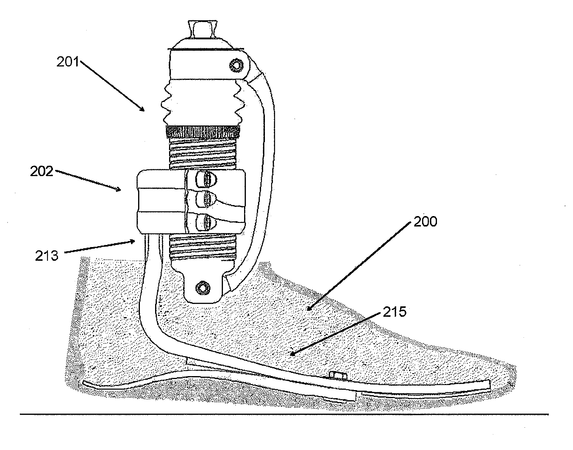
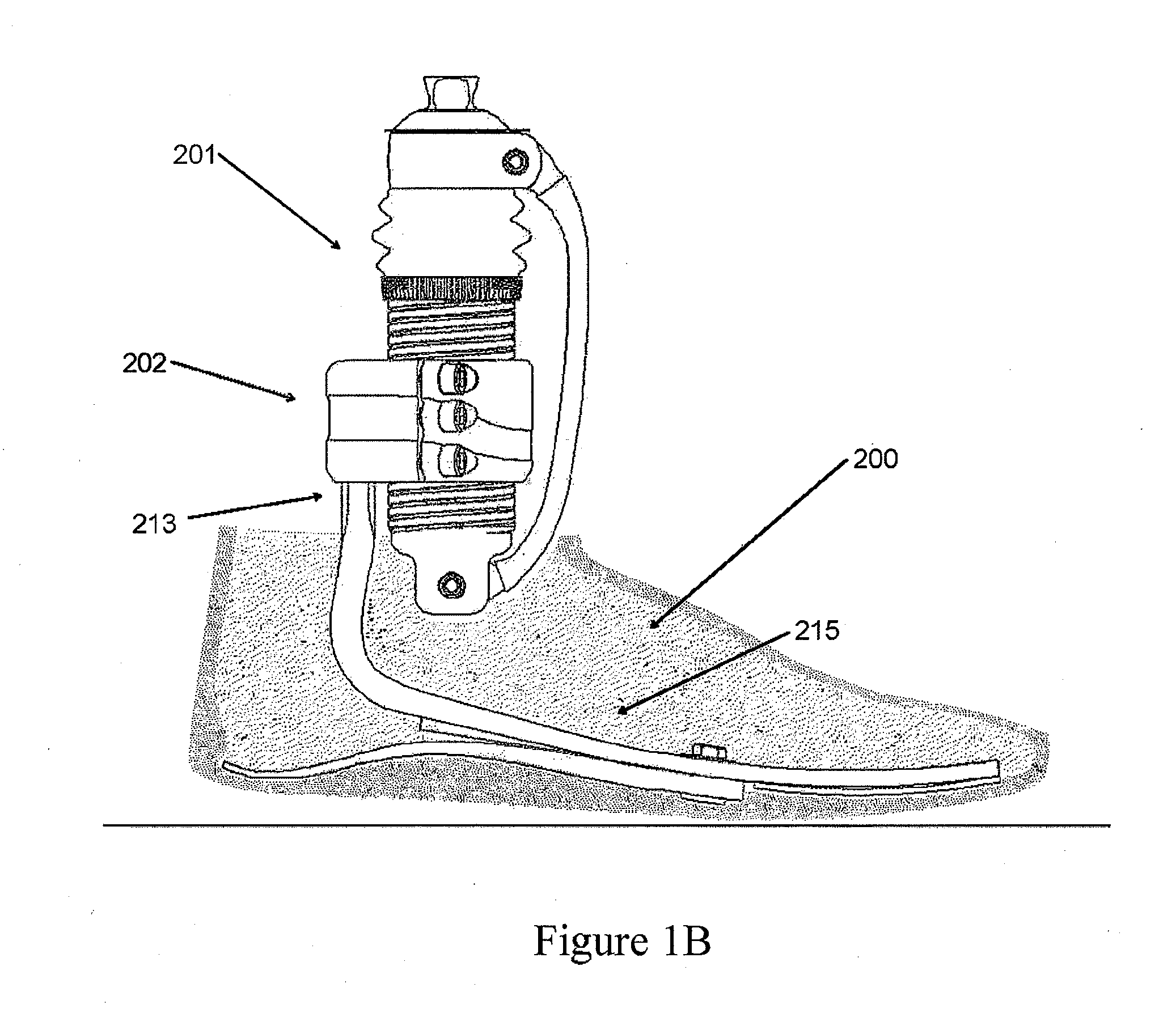
[0023]An objective of one or more embodiments described below is to provide a lightweight, low energy loss, vertical suspension system for prosthetic feet. The vertical suspension system enables rollover characteristics between heel strike and toe-off that are fit for everyday use and at the same time encourage highly active users through its suspension, energy return and lightness. Additionally, the substantially frictionless nature of the vertical suspension system results in substantially greater energy return than existing suspension systems, and is therefore well-suited for physically demanding activities such as running.

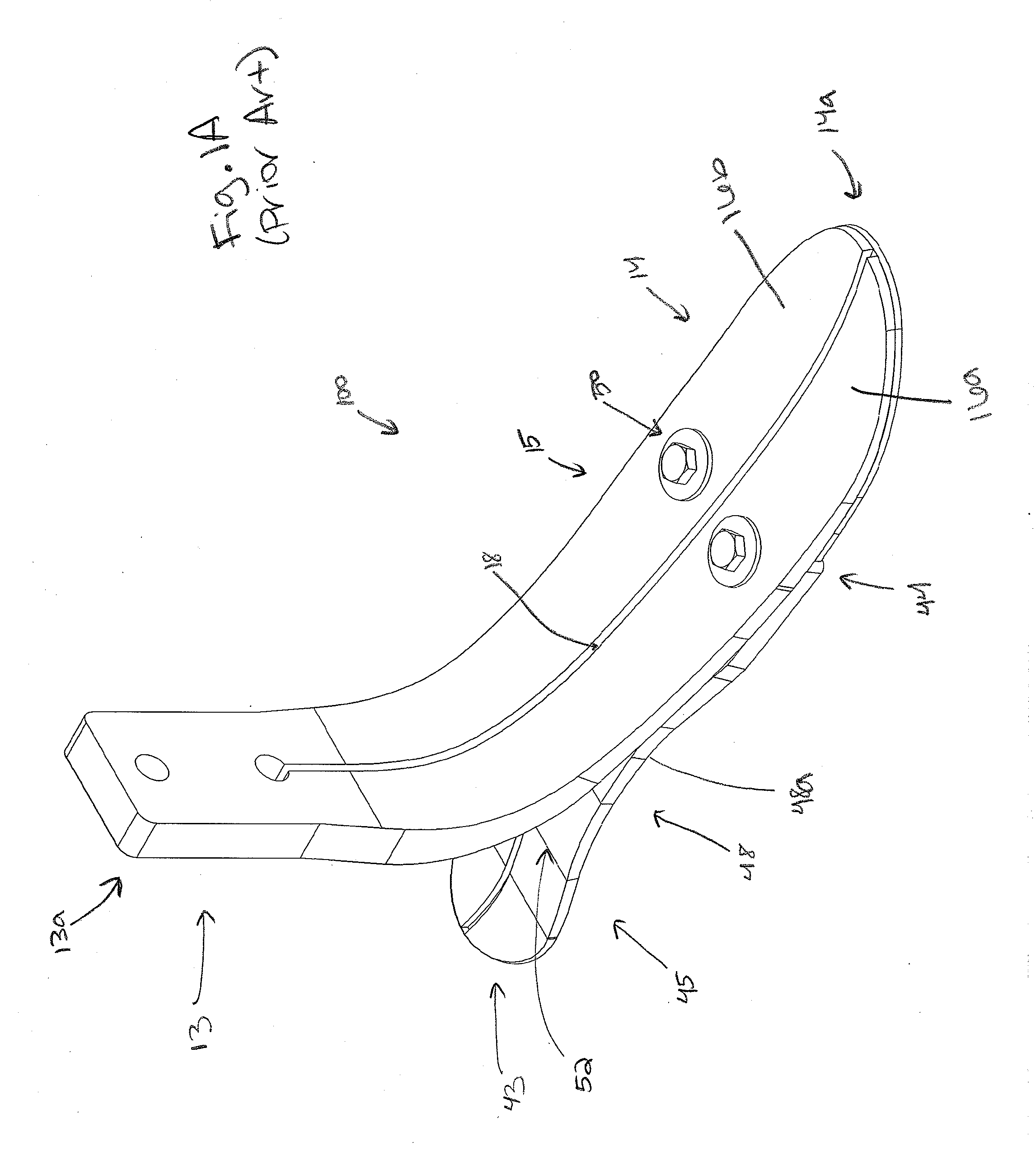
[0024]FIG. 1A shows a conventional prosthetic foot 100. The prosthetic foot 100 can have a foot member 15 that extends from a proximal section 13 to a distal section 14. In the illustrated embodiment, the proximal section 13 can be generally vertically oriented, and the distal section 14 can be generally horizontally oriented with the foot member 15 curving dow...


PUM


Abstract

A vertical suspension system for a prosthetic foot includes a first member operatively coupleable to an amputee's residual leg. The suspension system can also include a second member coupleable to a prosthetic foot. One or more upper leaf springs and one or more lower leaf springs extend between and are attached to the first and second members such that at least one of the ends of each leaf spring is rotationally fixed to the first or second members, where the upper an lower leaf springs are spaced apart from each other.

Description

CROSS-REFERENCE TO RELATED APPLICATIONS[0001]This application claims priority benefit of U.S. Provisional Application No. 61 / 539,207, filed Sep. 26, 2011, the entirety of which is hereby incorporated by reference herein.BACKGROUND[0002]1. Field[0003]The present application relates in certain embodiments to prosthetic devices. In particular, the present application in certain embodiments relates to a frictionless vertical suspension mechanism for a prosthetic foot.[0004]2. Description of the Related Art[0005]Prosthetic feet of different designs are well known in the art. The various conventional designs have sought to solve various limitations associated with prosthetic feet.[0006]Some prosthetic foot designs employ shock absorbing members (e.g., ankle members). However, such shock absorbing members tend to be relatively heavy and / or bulky. A common problem observed in prosthetic feet aiming for high travel suspension is that when in mid-stance, the bodyweight is supported by both th...

Claims


Application Information

Patent Timeline
Patent Type & Authority Applications(United States)
IPC IPC(8): A61F2/66
CPCA61F2/66A61F2002/6657A61F2002/5079A61F2002/5003A61F2002/6664A61F2002/607A61F2/60A61F2002/6614
Inventor LECOMTE, CHRISTOPHESKULASSON, BENEDIKTNIJIMAN, JEROEN
Owner OSSUR HF
Why Eureka
Try Eureka