Chainsaw with cutting chain tensioner

a chainsaw and chain tensioner technology, applied in the field of chainsaws, can solve the problems of chain bar shifting, chain link construction that is prone to becoming long, and chain bar may become slack, so as to reduce the play of the knob

Active Publication Date: 2013-04-11
ECHO INCORP
View PDF17 Cites 10 Cited by
  • Summary
  • Abstract
  • Description
  • Claims
  • Application Information

AI Technical Summary

Benefits of technology

[0019]In one form, the invention is directed to a saw having a power unit with a drive component and a housing for the power unit with a frame. A bar on the housing guides movement of an operatively positioned cutting chain, driven by the drive component, in an endless path. The bar is movable guidingly in opposite directions in a predetermined path relative to the housing to thereby vary tension upon an operatively positioned cutting chain. A bar fixing assembly has a knob that is turnable around a first axis relative to the housing in: a) a first direction to a tightened state wherein the bar is fixed relative to the housing; and b) a second direction, with the knob in the tightened state, to a loosened state wherein the bar can be moved relative to the housing in the predetermined path. A first assembly resiliently bears against the knob to at least one of: a) inhibit turning of the knob around the first axis; b) provide a sensory indication to a user grasping and turning the knob that the knob is moving around the first axis; and c) reduce play in the knob.
[0021]In one form, the saw further includes a tensioning assembly with an actuator that can be repositioned by a user's hand with the knob in the loosened state, without the need for separate tools, to thereby move the bar in the predetermined path.

Problems solved by technology

As the chainsaw is operated, there is a tendency of the chain bar to shift in a manner whereby the chain may become slackened.
Additionally, the chain has a link construction that is prone to becoming lengthened over extensive use periods.
Tool-operated tensioners, while functionally effective, have drawbacks.
If the necessary tools are for some reason not available, potentially the chainsaw will be inoperable.
Alternatively, a user risks that a slackened chain might become damaged or, in a worst case, separate from the bar as the chainsaw is being operated.
Further, even if the user has on hand the necessary tool(s), manipulation of a separate tool is inherently inconvenient.
This is particularly inconvenient in cold weather conditions and / or when there is precipitation.
The inconveniences associated with handling separate tools prompted the industry to develop tensioners that are characterized as “toolless”.
A failure of a component of a toolless system may render the entire chainsaw unusable until a repair is effected.
Complicated mechanisms often become expensive by reason of the high cost of the parts themselves, as well as their assembly.
Complicated designs inherently tend to be more prone to failure than those that are more simplified.
While the above types of mechanisms have been effective in terms of holding the operating knob in a desired position and preventing rattling thereof, they do have drawbacks.
Use of separate latching components, aside from generally requiring a relatively complicated design, requires a user to releasably set the latch each time the chain is re-tensioned.
This introduces a level of inconvenience to the operator.
Further, the cooperating structures on relatively movable components, that prevent loosening and rattle, generally require parts to act against each other in a manner whereby they are prone to wear, particularly after extended use of the chainsaw.
The design process is complicated by the fact that these objectives are often competing in nature.

Method used


Image

  • Chainsaw with cutting chain tensioner
  • Chainsaw with cutting chain tensioner
  • Chainsaw with cutting chain tensioner

Examples


Embodiment Construction

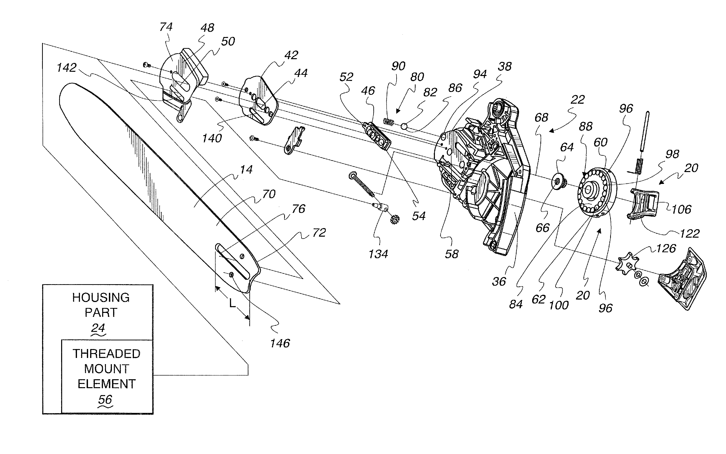
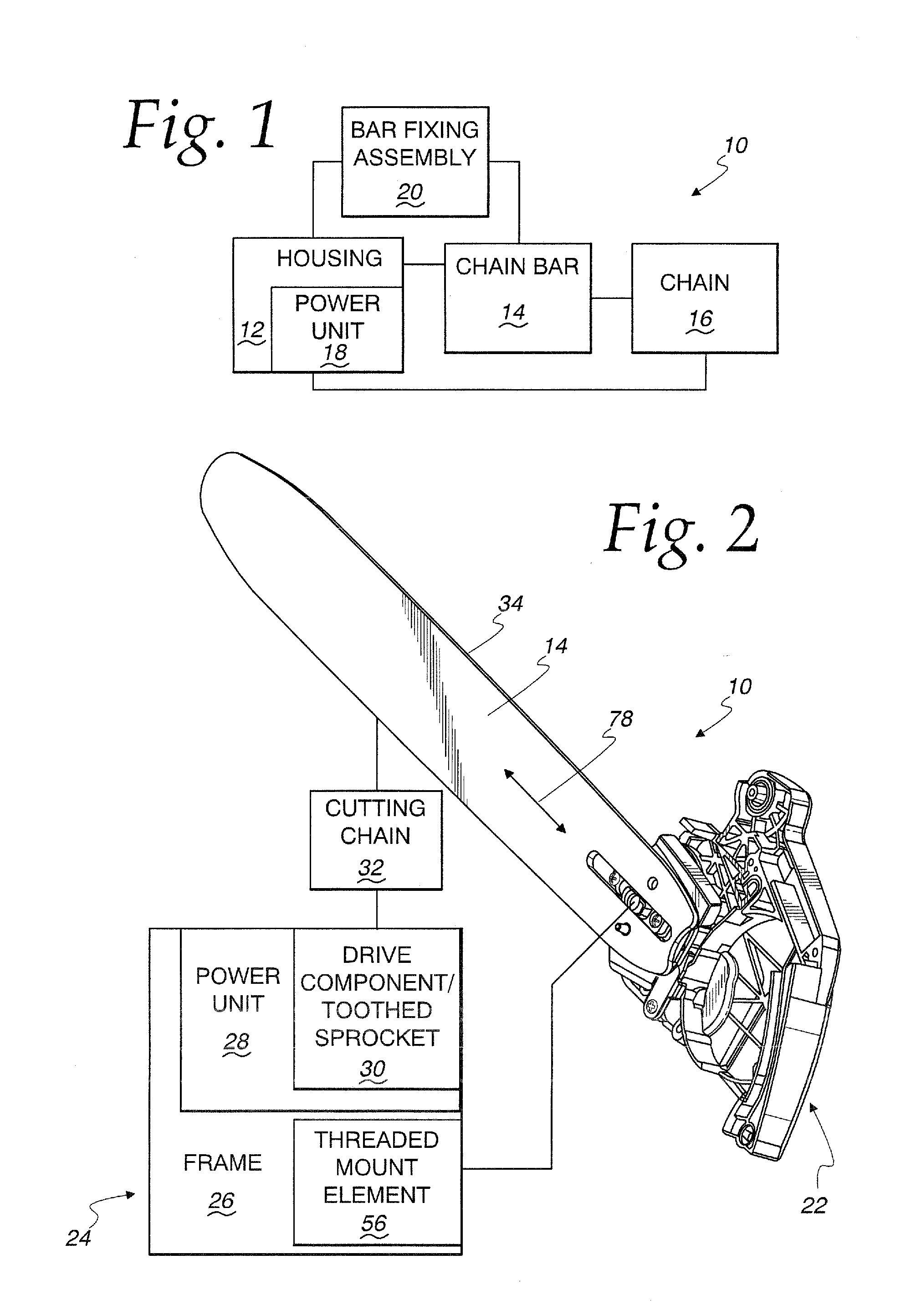
[0054]In FIG. 1, a saw of the type suitable for incorporation of the present invention is shown at 10. The saw 10 is shown in schematic form to encompass specific component forms, as described hereinafter, and variations thereof. The saw 10 has a housing 12 to which a chain bar 14 is attached. The chain bar 14 is movable guidingly relative to the housing 12 to thereby vary tension upon a cutting chain 16 that is trained around the chain bar 14 and a component on a power unit 18 through which the saw 10 is operated. The chain bar 14 is fixed in different positions by a bar fixing assembly 20. The invention herein is focused primarily upon the bar fixing assembly 20 and associated structure. The other components may take a wide variety of different forms and are of the type generally known to those skilled in the art. Exemplary saw structures are described in detail in U.S. Pat. Nos. 6,237,229 and 7,322,114, incorporated herein by reference. These well-known components will not be des...


PUM

PropertyMeasurementUnit
tensionaaaaaaaaaa
shapeaaaaaaaaaa
spherical shapeaaaaaaaaaa

Abstract

A saw having a power unit with a drive component and a housing for the power unit with a frame. A bar on the housing guides movement of an operatively positioned cutting chain driven by the drive component in an endless path. The bar is movable guidingly in opposite directions in a predetermined path relative to the housing to thereby vary tension upon an operatively positioned cutting chain. A bar fixing assembly has a knob that is turnable around a first axis relative to the housing in: a) a first direction to a tightened state; and b) a second direction to a loosened state. A first assembly resiliently bears against the knob to at least one of: a) inhibit turning of the knob around the first axis; b) provide a sensory indication to a user grasping and turning the knob that the knob is moving around the first axis; and c) reduce play in the knob.

Description

BACKGROUND OF THE INVENTION[0001]1. Field of the Invention[0002]This invention relates to chainsaws and, more particularly, to a chainsaw with a mechanism for selectively tensioning an endless cutting chain thereon.[0003]2. Background Art[0004]Chainsaws are commonly configured with a main housing that contains a power unit. The housing has operating handles thereon that allow a user to conveniently lift and reposition the chainsaw. A trigger is provided on one of the handles through which operating speeds for the chainsaw are controlled.[0005]The housing includes a frame to which a chain bar is operatively connected. The chain bar has a track for guiding movement of a chain in an endless path. With the chain bar operatively positioned, the chain can be trained around both the bar and a toothed component that is driven by the power unit.[0006]Virtually every chain bar is connected to its supporting frame so as to be translatable guidingly in a line generally parallel to the bar lengt...

Claims


Application Information

Patent Timeline
Patent Type & Authority Applications(United States)
IPC IPC(8): B27B17/14B23D57/02
CPCB27B17/14Y10T83/7239
Inventor PETERSON, BRENT
Owner ECHO INCORP
Why Eureka
Try Eureka