

Oil cooling system
a technology of oil cooling system and oil tank, which is applied in the direction of efficient propulsion technology, mechanical equipment, machines/engines, etc., can solve the problems of air-oil heat exchangers being larger and heavier, fuel flow may not be sufficient for engine or generator oil cooling,
- Summary
- Abstract
- Description
- Claims
- Application Information
AI Technical Summary
Benefits of technology
Problems solved by technology
Method used
Image

Examples
Embodiment Construction
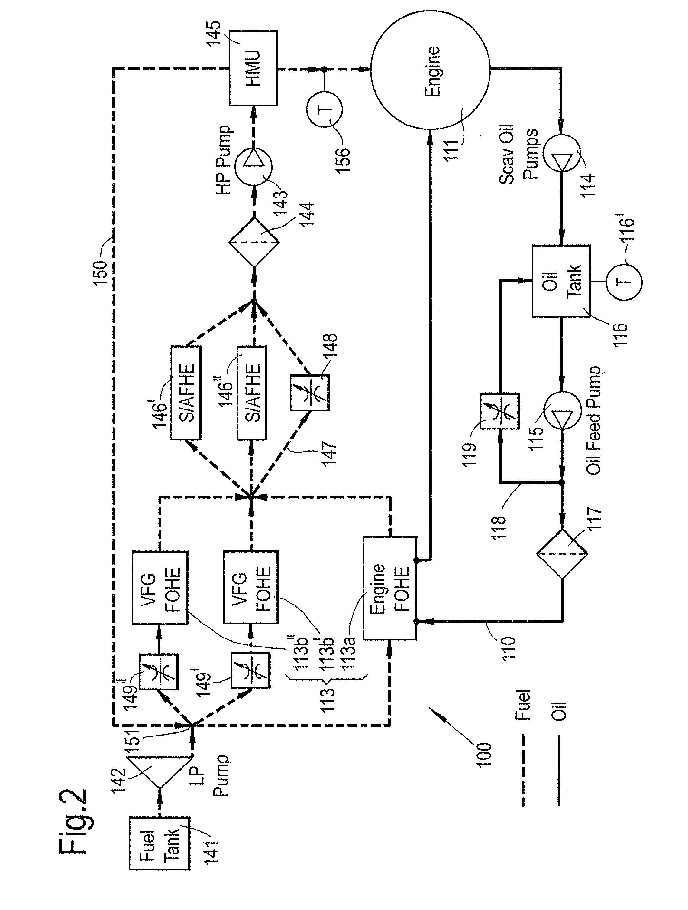
[0030]With reference to FIG. 2, an oil cooling system 100 according to a first example of the present invention comprises one or more fuel-oil heat exchangers 113, the fuel-oil heat exchangers using fuel for an engine 111 to cool one or more circulating flows of oil. The circulating flows of oil may circulate about one or more oil circuits.
[0031]A first oil circuit 110 may circulate oil around components of the engine 111, e.g. for cooling and / or lubricating purposes. The first oil circuit 110 may comprise a first pump 114 (e.g. a scavenger oil pump), an oil tank 116, a second pump 115 (e.g. an oil feed pump), a filter 117 and a fuel-oil heat exchanger 113a arranged in flow series in a circuit. The oil tank 116 may comprise a temperature probe 116′. The fuel-oil heat exchanger 113a may be arranged so that oil in the first oil circuit 110 is in thermal contact with the fuel. Oil from the fuel-oil heat exchanger 113a may return to the engine 111. Accordingly, the fuel for the engine m...
PUM
 Abstract
Description
Claims
Application Information