
Drive system for a wind turbine

a technology of drive system and wind turbine, which is applied in the direction of electric generator control, machine/engine, gearing, etc., can solve the problems of merely exposed to torsional stresses and represents a considerable simplification of installation and maintenance, and achieves the effect of less installation space and simplified installation

Active Publication Date: 2013-04-11
FLENDER GMBH
View PDF13 Cites 21 Cited by
  • Summary
  • Abstract
  • Description
  • Claims
  • Application Information

AI Technical Summary

Benefits of technology

The present invention provides a simplified and easier way to install and maintain a drive system for a work machine. It allows for the coupling flanges to be easily attached or detached from the shaft, making it easy to radially remove or integrate the drive system. The use of axially removable elastomer bolts also requires less installation space and allows for individual replacement. This leads to a more efficient and compact drive system.

Problems solved by technology

Thus the drive system is merely exposed to torsional stresses.
This represents a considerable simplification for installation and maintenance.

Method used


Image

  • Drive system for a wind turbine
  • Drive system for a wind turbine
  • Drive system for a wind turbine

Examples


Embodiment Construction

[0023]Throughout all the figures, same or corresponding elements may generally be indicated by same reference numerals. These depicted embodiments are to be understood as illustrative of the invention and not as limiting in any way. It should also be understood that the figures are not necessarily to scale and that the embodiments are sometimes illustrated by graphic symbols, phantom lines, diagrammatic representations and fragmentary views. In certain instances, details which are not necessary for an understanding of the present invention or which render other details difficult to perceive may have been omitted.

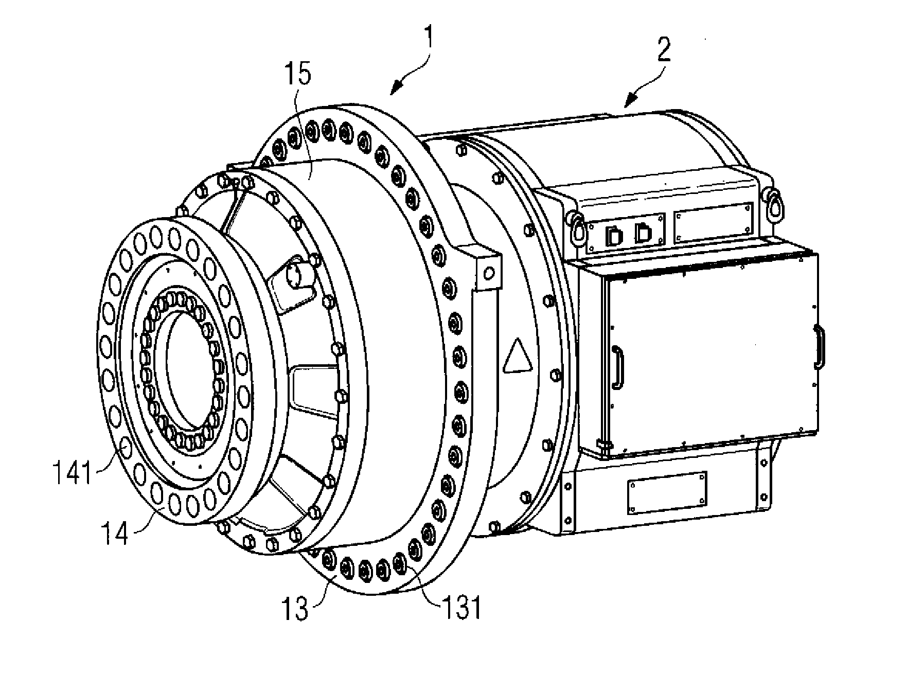
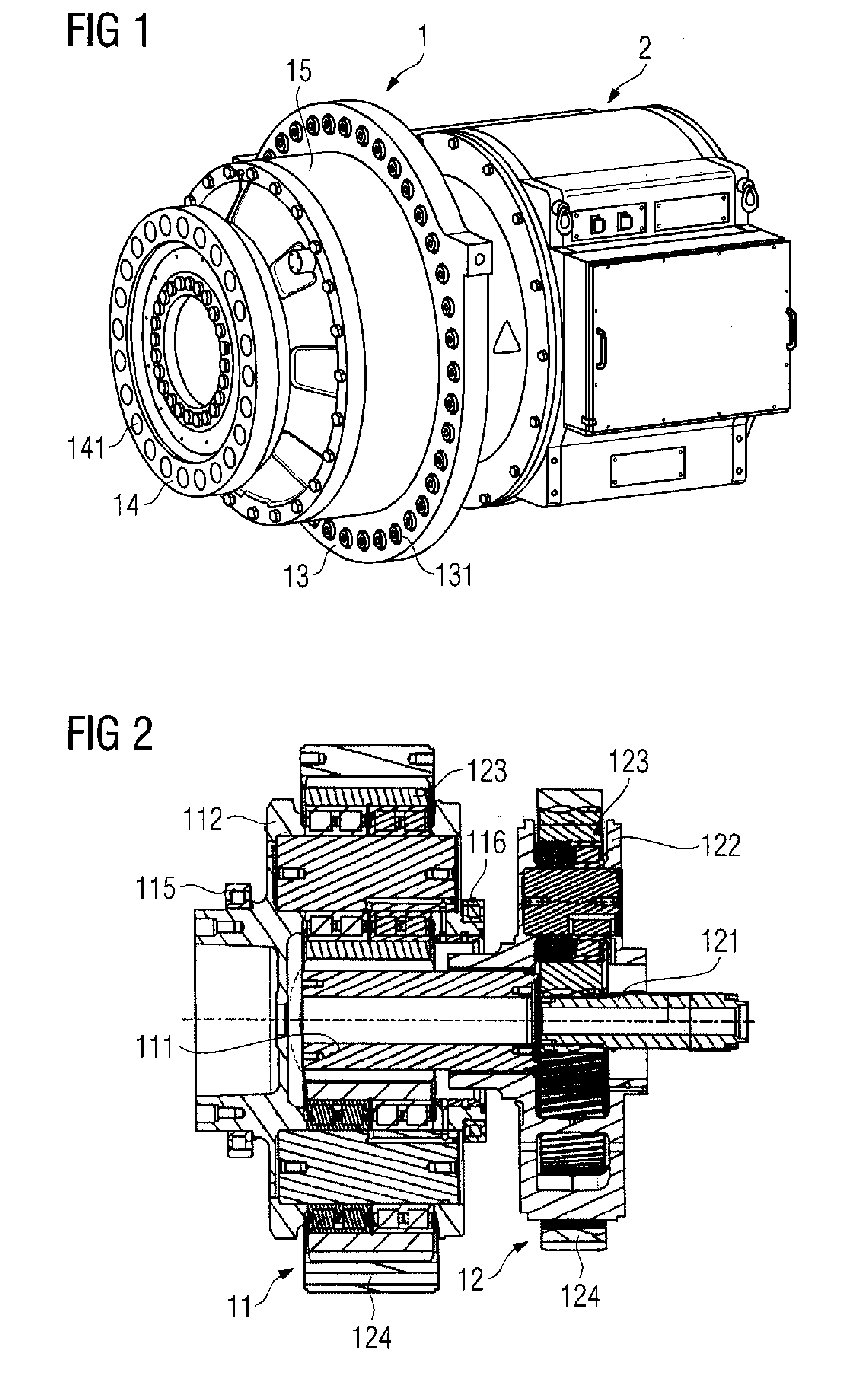
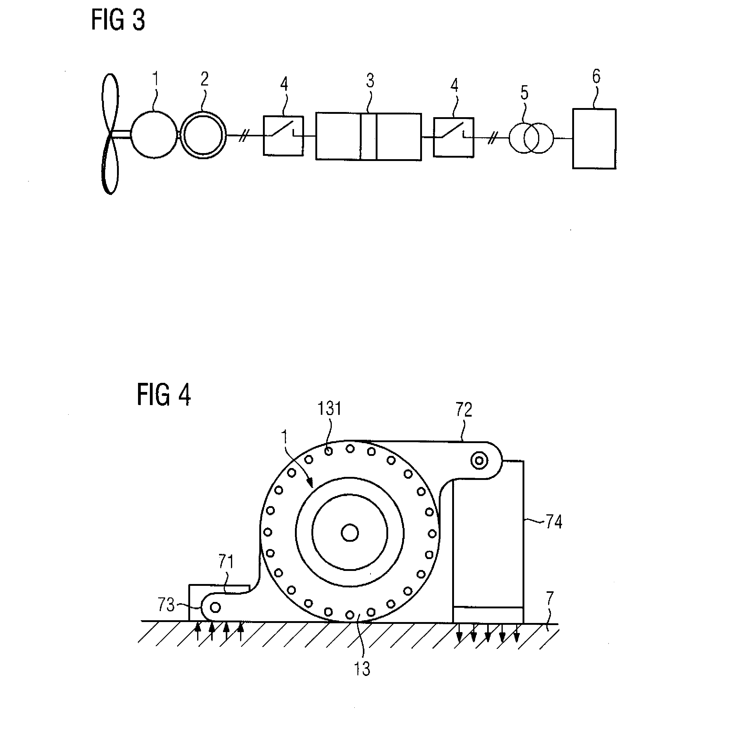
[0024]Turning now to the drawing, and in particular to FIG. 1, there is shown a drive system for a wind turbine having a transmission unit 1 with a coaxially constructed first 11 and second planet wheel stage 12. According to FIG. 2 each planet wheel stage 11, 12 comprises a hollow wheel 114, 124, several planet wheels 113, 123, a planet carrier 112, 122 and a sun wheel 111,...


PUM


Abstract

A drive system has a transmission unit comprising at least one planet wheel stage, which has a hollow wheel, several planet wheels, a planet carrier and a sun wheel. Furthermore, a first shaft associated with the transmission unit is provided, which has a coupling flange that can be connected to a work machine shaft or rotor shaft and is mounted via the planet carrier. The transmission unit and a motor unit or generator unit connected to a second shaft of the transmission unit are enclosed by a gear housing which has a cardanic circumferentially symmetric or partially symmetric suspension for connection to a supporting structural element of the wind turbine.

Description

CROSS-REFERENCES TO RELATED APPLICATIONS[0001]This application claims the priority of European Patent Application, Serial No. EP11002782, filed Apr. 4, 2011, pursuant to 35 U.S.C. 119(a)-(d), the content of which is incorporated herein by reference in its entirety as if fully set forth herein.BACKGROUND OF THE INVENTION[0002]The present invention relates to a drive system for a wind turbine.[0003]The following discussion of related art is provided to assist the reader in understanding the advantages of the invention, and is not to be construed as an admission that this related art is prior art to this invention.[0004]Besides slow-running gearless direct drive systems and medium-fast-running drive trains with one- or two-stage gearboxes, fast-running drive trains which have three or more gearbox stages and which are conceptually fundamentally different are also used in wind turbines at present. These drive train concepts each embrace a number of variants with modular, open and partia...

Claims


Application Information

Patent Timeline
Patent Type & Authority Applications(United States)
IPC IPC(8): F03D11/02
CPCF03D11/02F05B2260/301F05B2260/40311F05B2260/96Y02E10/722F05C2251/02F16H1/46F16H1/28F05C2225/00F03D15/00F16H57/08F16H57/025F16H57/028F03D80/70F03D15/10Y02E10/72
Inventor DINTER, RALF MARTINKLEIN-HITPASS, ARNOREIMERS, JAN-DIRK
Owner FLENDER GMBH
Learn More