Calibration method for automotive radar using phased array

a phased array and radar technology, applied in the direction of instruments, measuring devices, antennas, etc., can solve the problems of increased false alarms and missed detections, directional misalignment, and the inability of vehicular manufacturing process and installation methods of radar to allow for sufficient directional precision to be initially achieved, so as to improve the long-term accuracy of the radar operation, improve the operation, and improve the effect of operation

Inactive Publication Date: 2013-04-11
TOYOTA JIDOSHA KK
View PDF8 Cites 41 Cited by
  • Summary
  • Abstract
  • Description
  • Claims
  • Application Information

AI Technical Summary

Benefits of technology

[0008]A method of improving operation a phased-array radar mounted on a vehicle includes calibrating the adjustable phase shifters using an internal self-test signal, and compensating for mechanical misalignment by detecting a radar target at along a detected direction. The difference between the detected direction and the true direction of the radar target relative to the vehicle is used to determine a misalignment factor, such as a misalignment angle. The misalignment factor is used to correct measurements made with the phased-array radar, to compensate for the actual mechanical misalignment, improving the operation (e.g. the accuracy) of the phased-array radar. An internal self-test signal may be generated at any suitable time by a test oscillator within the phased array radar, and conveyed along a self-test line running proximate the adjustable phase shifters.
[0009]The adjustable phase shifters may be re-calibrated at intervals during operation of the phased array radar using the internal self-test signal, to further improve the long-term accuracy of the radar operation. For a radar including both transmit and receive functions, the self-test signal is preferably generated (and the phase shifters calibrated) while the transmit antenna is not transmitting. The calibration may be relatively fast, for example completed in less than a second, and so calibration of the phase shifters may occur at intervals during operation of the radar, while the vehicle is in normal use. Calibration may occur, for example, during the following circumstances: when the radar is first turned on, when the vehicle is stopped, when the vehicle is moving slowly, whenever ambient conditions (e.g. temperature) change significantly, or at time intervals such as every hour. This flexibility in internal calibration has never before been possible.
[0010]For the first time, an automotive radar can be both electronically and mechanically calibrated in a simple process, for example available routinely at a dealer or service station. The electronic calibration of the phase shifters may be achieved by pressing a button on the radar housing, or achieved automatically at intervals. The mechanical calibration only requires a single radar target (though more than one may be used in some cases) at a known angle relative to the vehicle on which the radar is mounted.

Problems solved by technology

Directional misalignment gives increased false alarms and missed detections.
The vehicular manufacturing process and installation methods of the radar typically do not allow for sufficient directional precision to be initially achieved, due to cost considerations.

Method used


Image

  • Calibration method for automotive radar using phased array
  • Calibration method for automotive radar using phased array
  • Calibration method for automotive radar using phased array

Examples


Embodiment Construction

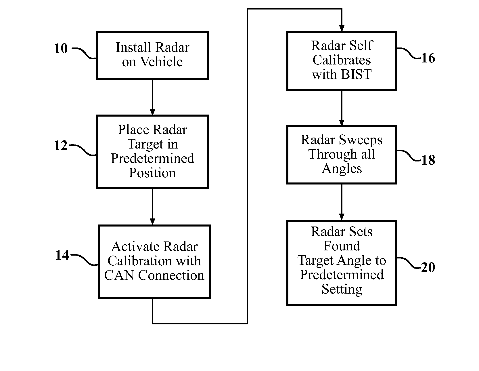
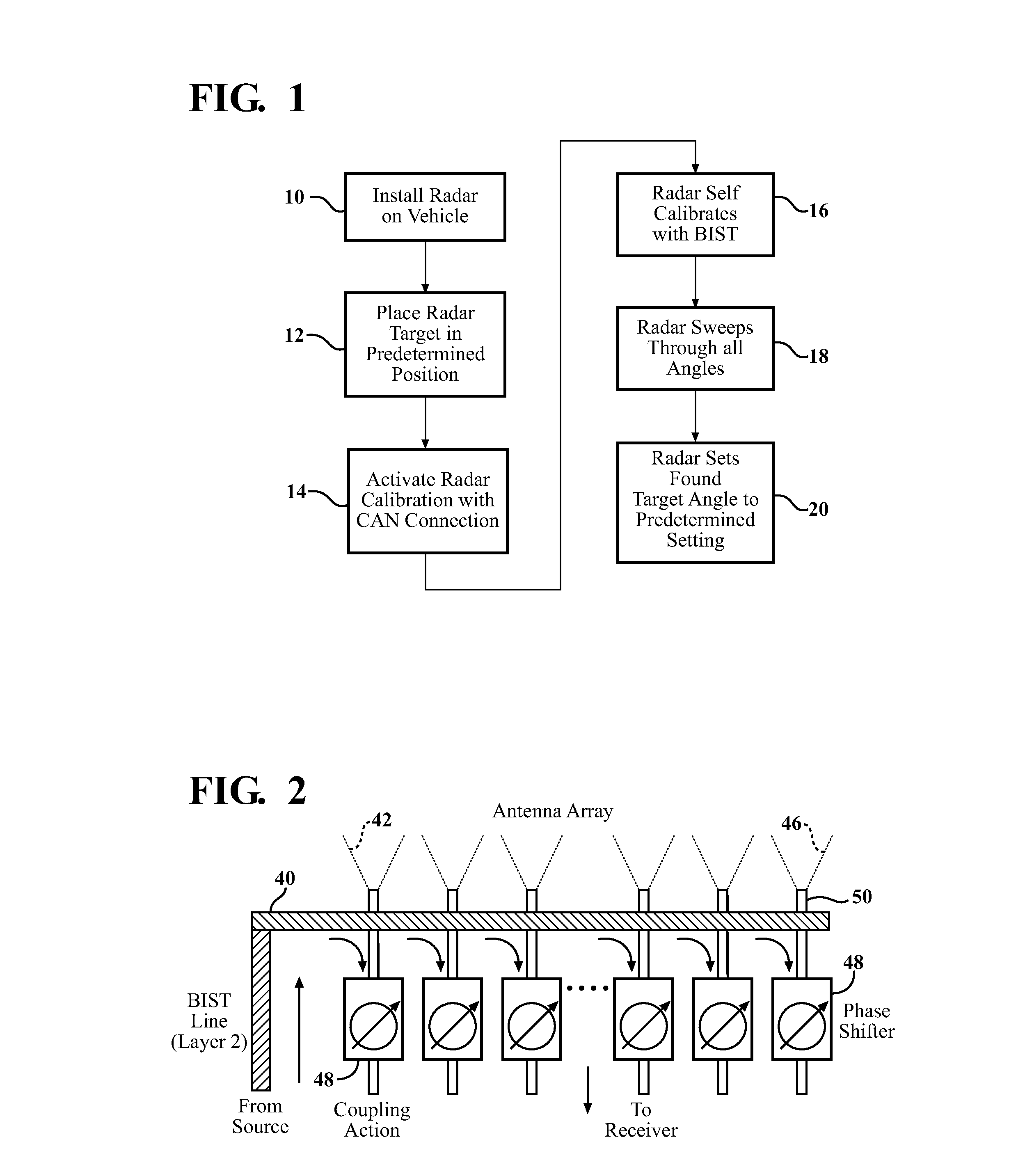
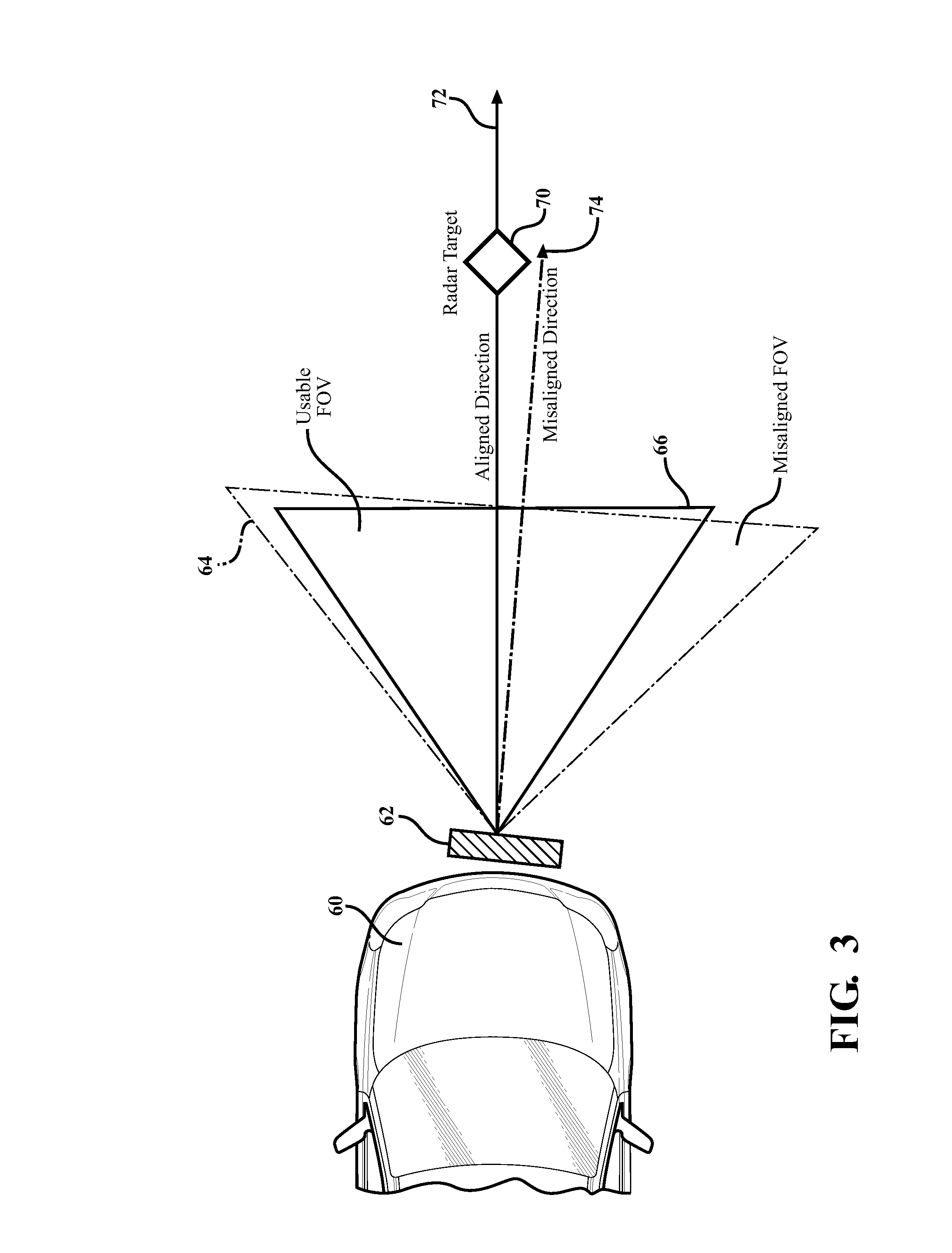
[0019]Examples of the present invention provide improved apparatus and methods for obtaining directional alignment of a radar apparatus, in particular alignment of an automotive radar using a phased array with the direction of motion of a vehicle. An example approach includes provision of a built in self-test line within the radar apparatus. This self-test line, also referred to herein as a BIST line, may comprise a conducting track that runs proximate the antenna array elements or connections thereto.

[0020]In an example approach, an oscillator signal injected into the BIST line by a test oscillator is detected by the receive circuit through a coupling action between the BIST line and the antenna elements or electrical connections thereto. The calibration is performed while the transmit antenna is turned off. A BIST line may be supported on a separate substrate layer, for example underneath the array of phase shifters. Other configurations are possible, for example by running the BI...


PUM


Abstract

Examples of the present invention include calibration methods for phased array radar apparatus. The calibration methods include an electronic calibration of phase shifters, and compensation for mechanical misalignment. Approaches are particularly useful for automotive radar, and may be used for initial calibration after installation on a factory line, or at later times such as at a service station whenever recalibration becomes necessary.

Description

FIELD OF THE INVENTION[0001]The invention relates to calibration methods for radar apparatus, in particular automotive radars.BACKGROUND OF THE INVENTION[0002]Directional alignment is very important to the proper functioning of a radar apparatus. Automotive radar should be aligned in the direction of vehicular travel with precision, otherwise the radar will malfunction. Directional misalignment gives increased false alarms and missed detections.[0003]The vehicular manufacturing process and installation methods of the radar typically do not allow for sufficient directional precision to be initially achieved, due to cost considerations. A calibration method to compensate for any misalignment would be extremely useful.SUMMARY OF THE INVENTION[0004]Examples of the present invention include calibration methods for a radar apparatus using phased array scanning techniques. The calibration method is particularly useful for automotive radar, and may be used for initial calibration after inst...

Claims


Application Information

Patent Timeline
Patent Type & Authority Applications(United States)
IPC IPC(8): G01S7/40G01S13/931
CPCG01S7/4004H01Q3/267G01S7/4026G01S2007/406G01S2013/0245G01S13/931G01S2007/4069G01S7/4052G01S2007/4082G01S2013/9375G01S2007/403G01S2013/93271G01S7/403G01S7/406G01S7/4069G01S7/4082
Inventor LEE, JAE SEUNGSCHMALENBERG, PAUL DONALD
Owner TOYOTA JIDOSHA KK
Why Eureka
Try Eureka