Stereo-scopic image panel, stereo-scopic image display apparatus having the same and driving method thereof

a stereoscopic image and display apparatus technology, applied in the direction of optics, electrical apparatus, instruments, etc., can solve the problems of deteriorating stereoscopic image quality, difficult bonding, inconvenient glasses-putting, etc., to minimize discontinuity, minimize crosstalk, and smooth and free stereoscopic image

Active Publication Date: 2013-04-11
ELECTRONICS & TELECOMM RES INST
View PDF6 Cites 11 Cited by
  • Summary
  • Abstract
  • Description
  • Claims
  • Application Information

AI Technical Summary

Benefits of technology

[0019]According to a stereoscopic image panel, a stereoscopic image display apparatus including the stereoscopic image panel, and a method of driving the stereoscopic image panel of the present invention, it is possible to implement a smooth and free stereoscopic image by minimizing discontinuity generated when moving a barrier and minimizing crosstalk.
[0020]Further, the technical effect of the present invention described above is not limited to the effect described above and other technical effects not stated herein can be clearly understood by those skilled in the art from the following description.

Problems solved by technology

However, the glasses type has a problem in that it is inconvenient to put on glasses when watching a stereoscopic image and eye strain is caused in long time watching.
Therefore, the published invention may have a problem in that the quality of a stereoscopic image is deteriorated and bonding becomes difficult.

Method used


Image

  • Stereo-scopic image panel, stereo-scopic image display apparatus having the same and driving method thereof
  • Stereo-scopic image panel, stereo-scopic image display apparatus having the same and driving method thereof
  • Stereo-scopic image panel, stereo-scopic image display apparatus having the same and driving method thereof

Examples


Embodiment Construction

[0026]Hereinafter, a stereoscopic image panel, a stereoscopic image display apparatus including the stereoscopic image panel, and a method of driving the stereoscopic image panel in accordance with the present invention are described in detail with reference to the accompanying drawings.

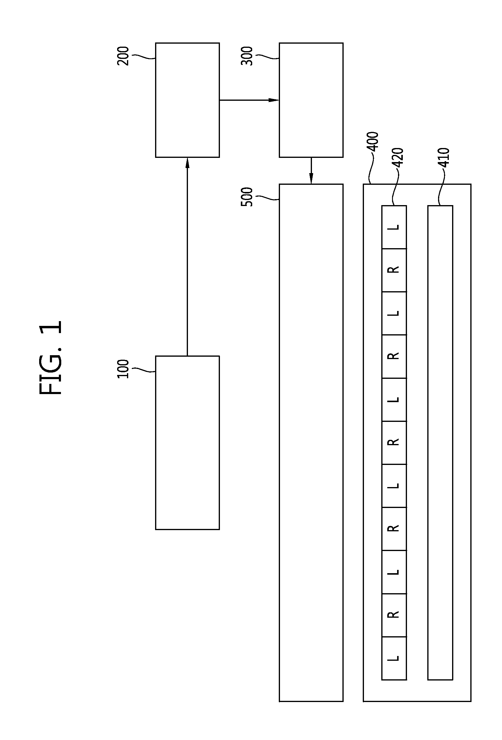
[0027]FIG. 1 is a configuration diagram showing a stereoscopic image display apparatus according to an exemplary embodiment of the present invention.

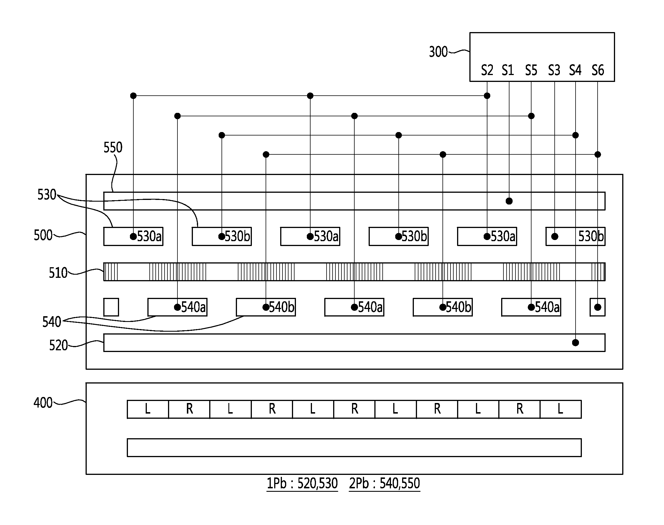
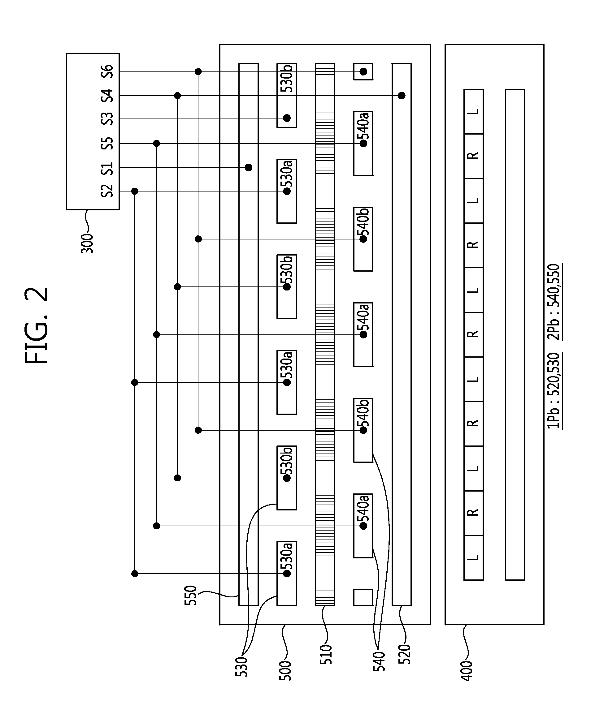
[0028]As shown in FIG. 1, the stereoscopic image display apparatus includes a measuring unit 100, a control unit 200, a driving circuit unit 300, an image panel 400, and a stereoscopic image panel 500.

[0029]The measuring unit 100 is provided to measure the positional information of a viewer, such as the distance from the viewer, the left and right positions, and face inclination. A measuring sensor and a camera may be used as the measuring unit 100. For example, an IR (Infrared Ray), ultrasonic waves or a laser sensor may be selectively used as the measu...


PUM

PropertyMeasurementUnit
driving voltageaaaaaaaaaa
electric fieldaaaaaaaaaa
timeaaaaaaaaaa

Abstract

A stereoscopic image panel according to the present invention includes: a liquid crystal layer; a first parallax barrier layer including a first electrode unit adjacent to one side of the liquid crystal layer and a second electrode unit opposite the other side of the liquid crystal layer; and a second parallax barrier layer including a third electrode unit opposite one side of the liquid crystal layer, between the liquid crystal layer and the first electrode unit, and a fourth electrode unit positioned adjacent to the second electrode unit, wherein the second electrode unit is positioned between the liquid crystal layer and the fourth electrode unit.

Description

CROSS-REFERENCE TO RELATED APPLICATIONS[0001]This application claims the benefit of priority of Korean Patent Application No. 10-2011-0101084 filed on Oct. 5, 2011, all of which is incorporated by reference in their entirety herein.BACKGROUND OF THE INVENTION[0002]1.Field of the Invention[0003]The present invention relates to a stereoscopic image panel, a stereoscopic image display apparatus having the same, and a driving method thereof, and more particularly, to a stereoscopic image panel that provides a glasses-free stereoscopic image, an stereoscopic image display apparatus having the stereoscopic image panel, and a method of driving the stereoscopic image panel.[0004]2. Discussion of the Related Art[0005]In general, the technology related to stereoscopic image display apparatuses is used in various fields, not only in the image-related field, but the aerospace industry and the art industry, including consumer-electronics and telecommunication industries. The stereoscopic image d...

Claims


Application Information

Patent Timeline
Patent Type & Authority Applications(United States)
IPC IPC(8): G02F1/1335G02B30/31
CPCG02F1/1335H04N13/0409H04N13/0475G02F1/134309H04N13/0479G02B27/2214H04N13/0477H04N13/31H04N13/373H04N13/376H04N13/378G02B30/31G09G3/36G02B30/00G02B30/27
Inventor LEE, HYUNLEE, EUNG DON
Owner ELECTRONICS & TELECOMM RES INST
Why Eureka
Try Eureka