Swing device for construction machine

a construction machine and swing device technology, applied in mechanical devices, transportation and packaging, gearing, etc., can solve the problems of inconvenient integration of the motor shaft of the hydraulic motor and the motor shaft of the electric motor, the coupling portion of the motor shaft on the hydraulic motor side and the motor shaft on the electric motor side becoming undesirable worn, etc., to achieve the effect of enhancing the operation efficiency

Active Publication Date: 2013-04-11
NIHON KENKI CO LTD
View PDF4 Cites 10 Cited by
  • Summary
  • Abstract
  • Description
  • Claims
  • Application Information

AI Technical Summary

Benefits of technology

[0020]With this arrangement, when the operation of mounting or dismounting the reduction gear lower flange portion to or from the upper revolving structure is performed by using a fastening tool from above the hydraulic motor, the power supply box and various detectors mounted on the electric motor do not interfere with the fastening tool, so that it is possible to enhance the operational efficiency in this mounting or dismounting operation.

Problems solved by technology

However, in a case where a hybrid type swing device is configured by combining a hydraulic motor and an electric motor manufactured separately by different manufacturers, it is difficult to integrate the motor shaft of the hydraulic motor and the motor shaft of the electric motor as in the above-described conventional art.
For this reason, there is a problem in that in a case where this lubricant has been consumed, the coupling portions of the motor shaft on the hydraulic motor side and the motor shaft on the electric motor side become undesirably worn at an early period.

Method used


Image

  • Swing device for construction machine
  • Swing device for construction machine
  • Swing device for construction machine

Examples


Embodiment Construction

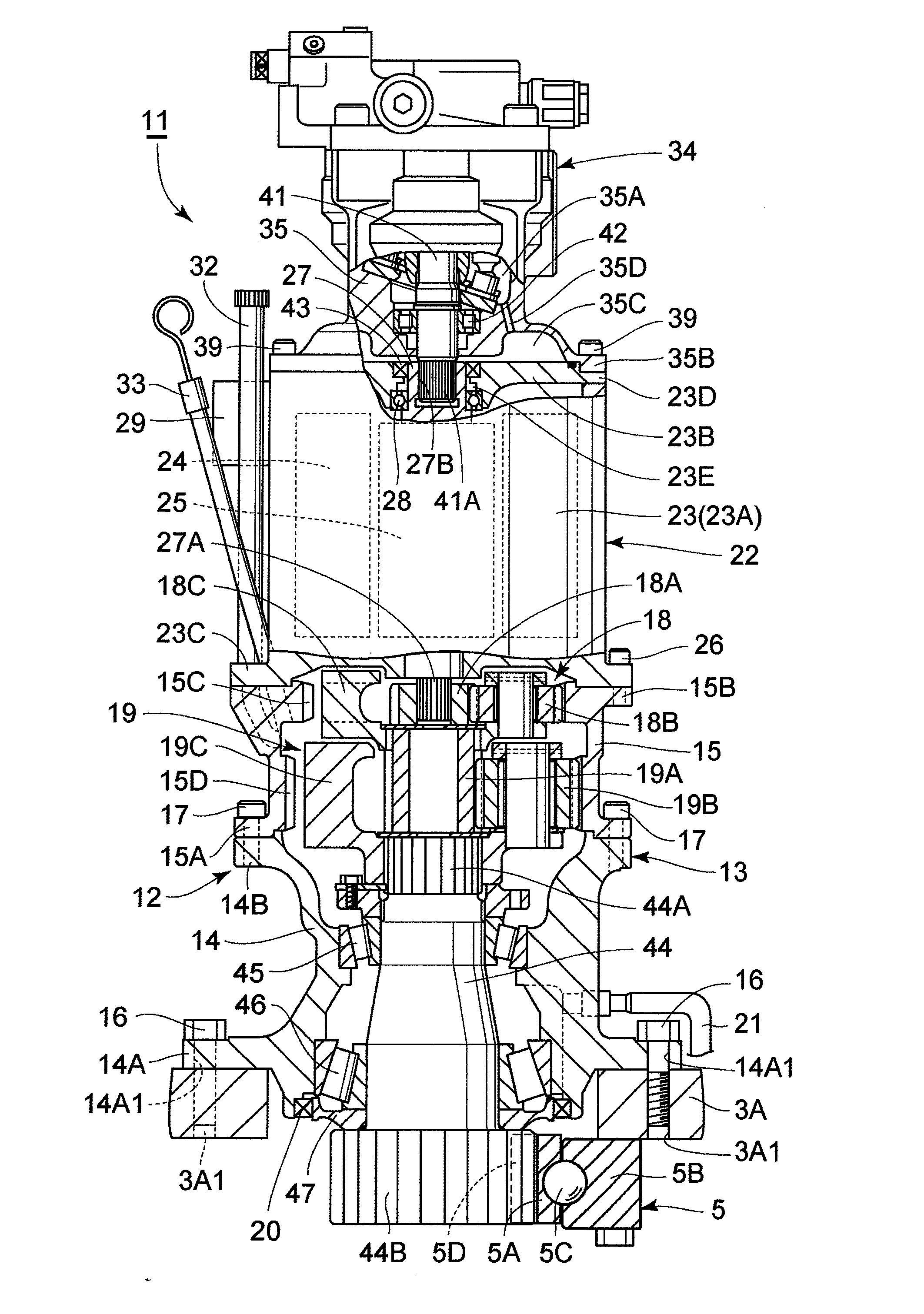
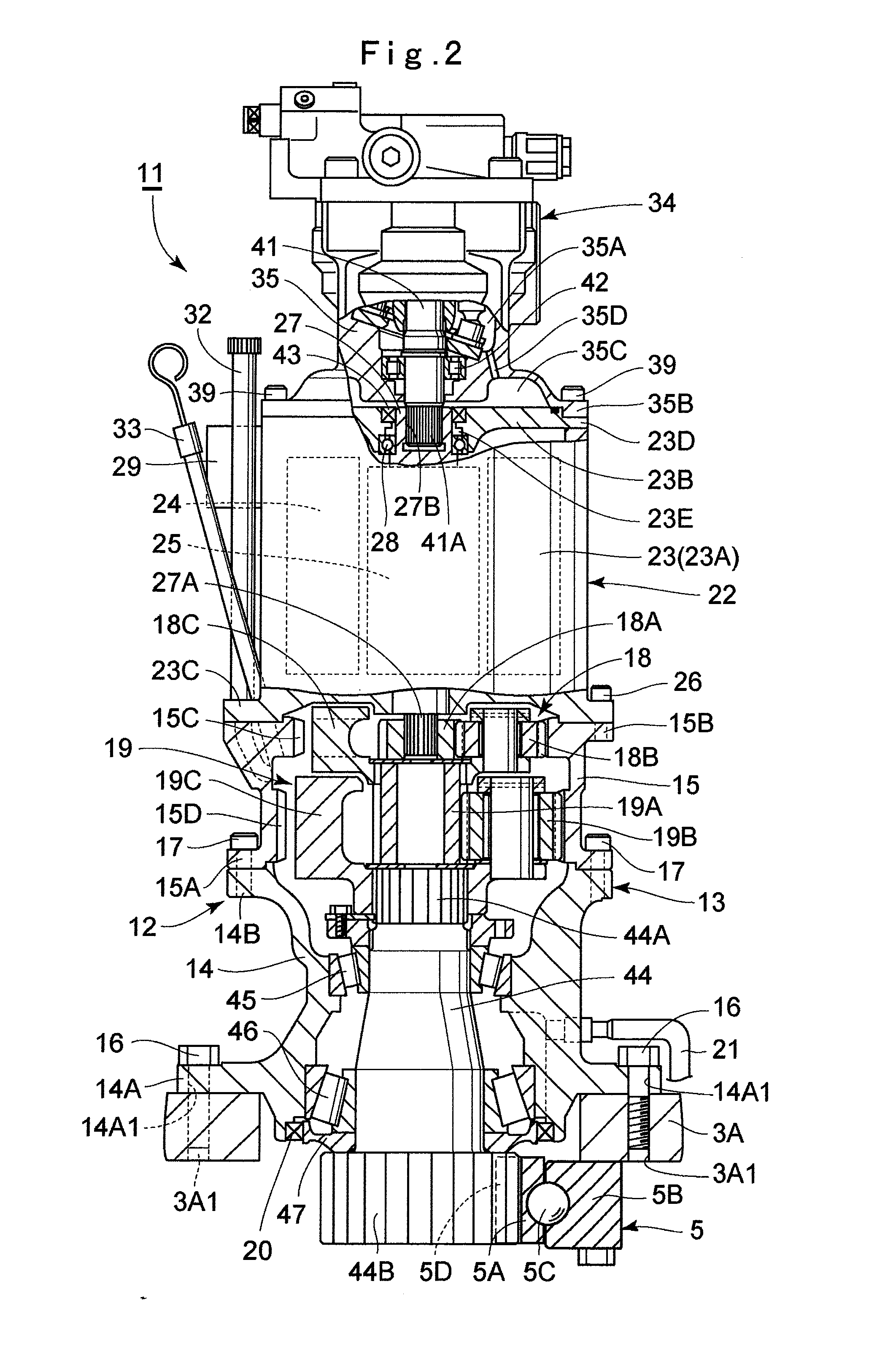
[0027]Hereafter, an embodiment of a swing device for a construction machine in accordance with the present invention will be in detail explained with reference to the accompanying drawings by taking a case in which the swing device for a construction machine is applied to a hydraulic excavator as an example swing device.

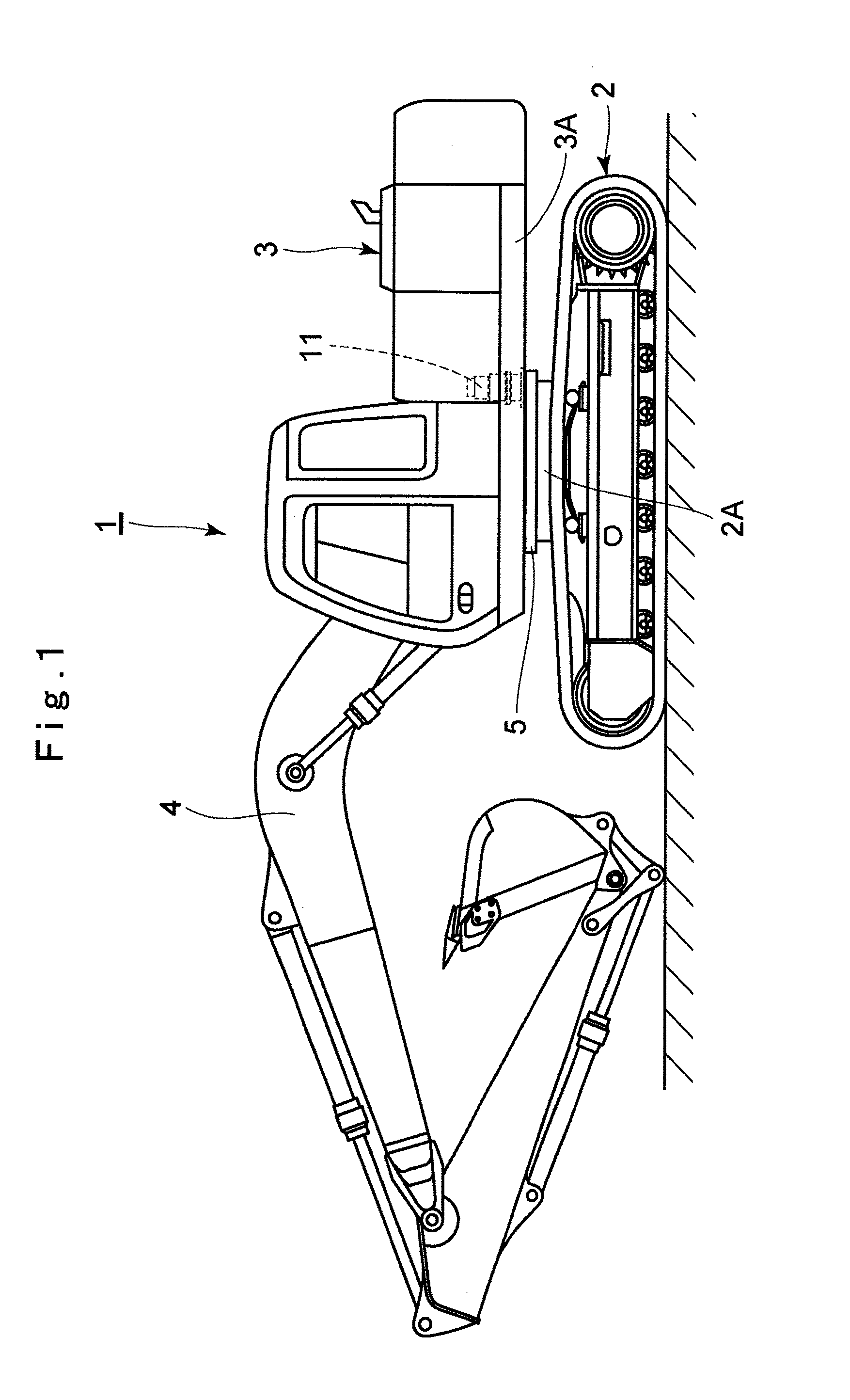
[0028]In the drawings, designated at 1 is a hydraulic excavator which is a typical example of construction machines. The hydraulic excavator 1 is largely constituted by an automotive crawler type lower traveling structure 2 and an upper revolving structure 3 which is swingably mounted on the lower traveling structure 2. A working mechanism 4 is provided liftably on the front side of the upper revolving structure 3. A below-described revolving ring 5 is provided between the lower traveling structure 2 and the upper revolving structure 3, and the upper revolving structure 3 is revolvably supported on the lower traveling structure 2 by means of the revolving ring 5.

[002...


PUM


Abstract

A reduction gear is mounted on a revolving frame, and an electric motor having an electric motor shaft is disposed on the reduction gear. A hydraulic motor having a shaft is disposed on an upper side of the electric motor. A shaft insertion hole through which an upper end side of the electric motor shaft is inserted is provided in a lid portion of an electric motor casing. A male spline portion provided on the hydraulic motor shaft is spline-coupled to a female spline portion provided on the electric motor shaft. A bearing is provided between the shaft insertion hole and the electric motor shaft, and a pressure tight seal is provided by being located upwardly of the bearing. Hence, spline coupling portions of the female spline portion and the male spline portion are constantly lubricated by making use of drain oil which has leaked from the hydraulic motor.

Description

TECHNICAL FIELD[0001]The present invention relates to a swing device for a construction machine which is used in a construction machine such as a hydraulic excavator, a hydraulic crane, or the like and which revolves an upper revolving structure on a lower traveling structure.BACKGROUND ART[0002]Generally, a hydraulic excavator as a typical example of construction machines is largely constituted by an automotive lower traveling structure, an upper revolving structure which is swingably mounted on the lower traveling structure by means of a revolving ring, and a working mechanism provided on the front side of the upper revolving structure. A swing device is provided between the lower traveling structure and the upper revolving structure, and as this swing device is operated, the upper revolving structure is adapted to revolve on the lower traveling structure.[0003]In this instance, the swing device is generally comprised of a reduction gear which is mounted on the upper revolving str...

Claims


Application Information

Patent Timeline
Patent Type & Authority Applications(United States)
IPC IPC(8): E02F9/12E02F9/20
CPCB60L2200/40E02F9/123E02F9/126E02F9/2095F16H1/46E02F9/12E02F9/20E02F9/202
Inventor UZAWA, NOBUOOJIMA, MITSUGUISHIKAWA, KOUJISATAKE, HIDETOSHI
Owner NIHON KENKI CO LTD
Why Eureka
Try Eureka