Apparatuses and methods for providing a secondary reflector on a solar collector system

a solar collector and secondary reflector technology, applied in solar heat systems, solar energy generation, lighting and heating apparatus, etc., can solve the problems of focusing errors, geometrically dependent optical losses, and the least a portion of reflected sunlight to be missed, so as to achieve the effect of minimizing misalignmen

Inactive Publication Date: 2013-04-18
GEAR SOLAR
View PDF1 Cites 17 Cited by
  • Summary
  • Abstract
  • Description
  • Claims
  • Application Information

AI Technical Summary

Benefits of technology

[0012]In accordance with various embodiments of the present invention as described herein, an additional solar collector system is provided. The system generally comprises: a frame assembly comprising a first support member, a second support member, and a third support member, the first, second, and third support members being operatively mounted relative to one another so as to define a unitary pivot axis; a primary reflector, the primary reflector being operatively attached to the first support member; a secondary reflector, the secondary reflector being operatively attach

Problems solved by technology

However, focusing errors and thus geometrically dependent optical losses occur in parabolic trough collectors due to a variety of factors.
For example, the mirror has a certain total shape tolerance, which may involve some degree of waviness, both of which lead to focusing errors.
Further, the positioning of the mirror during assembly is only possible to within certain tolerances, likewise causing at least a portion of the reflected sunlight to miss (e.g., not intercept) the elongated receiver tube.
Self-deformation (e.g., warping), manufacturing, and assembly tolerances of the steel structure, on which the parabolic trough collector is built, may also lead to inefficiencies.
External factors such as the non-limiting examples of wind and

Method used


Image

  • Apparatuses and methods for providing a secondary reflector on a solar collector system
  • Apparatuses and methods for providing a secondary reflector on a solar collector system
  • Apparatuses and methods for providing a secondary reflector on a solar collector system

Examples


Embodiment Construction

[0033]Various embodiments of the present invention will now be described more fully hereinafter with reference to the accompanying drawings, in which some, but not all embodiments of the invention are shown. Indeed, embodiments of the invention may be embodied in many different forms and should not be construed as limited to the embodiments set forth herein. Rather, these embodiments are provided so that this disclosure will satisfy applicable legal requirements. Unless otherwise defined, all technical and scientific terms used herein have the same meaning as commonly known and understood by one of ordinary skill in the art to which the invention relates. The term “or” is used herein in both the alternative and conjunctive sense, unless otherwise indicated. Like numbers refer to like elements throughout.

[0034]Overview

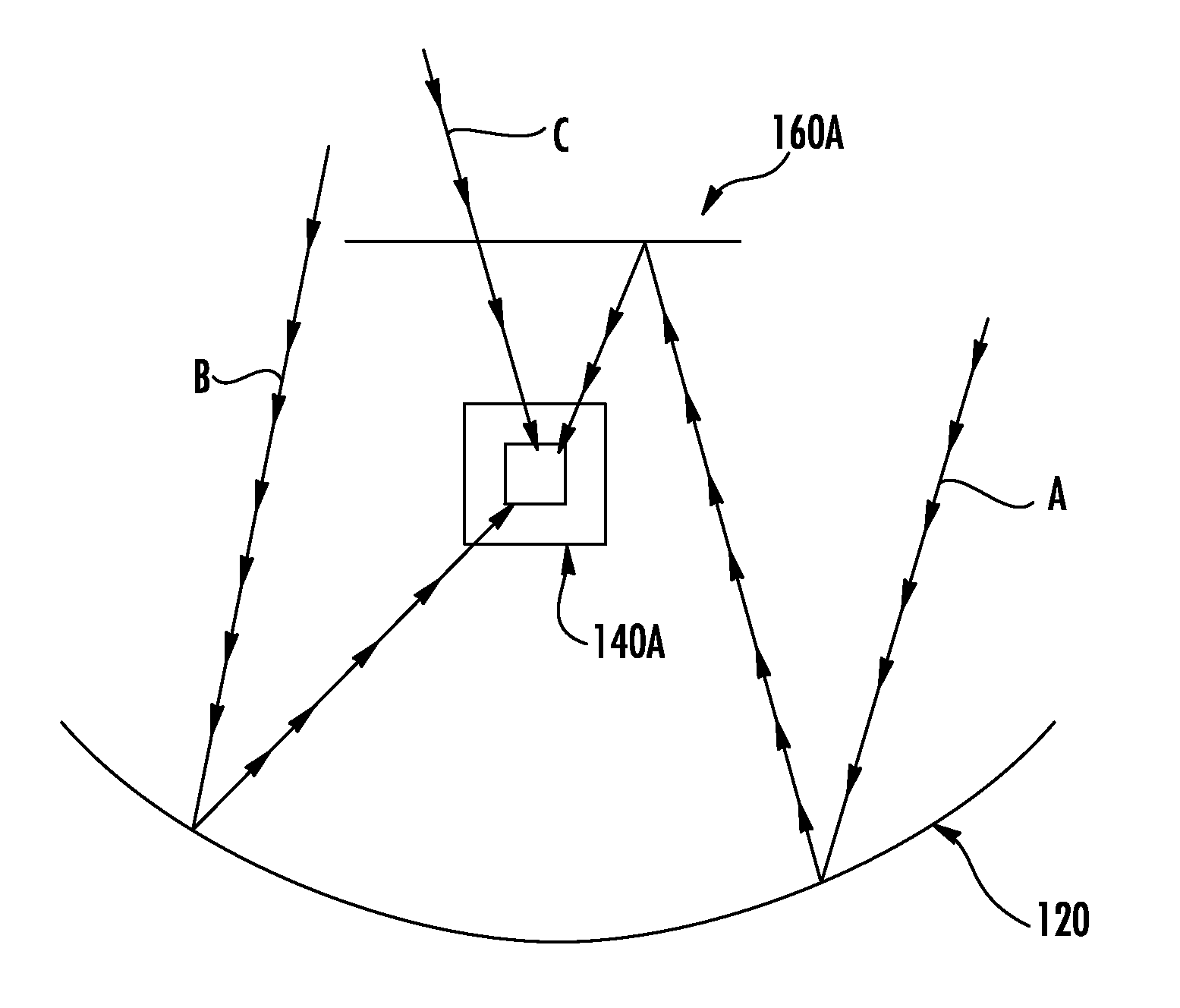
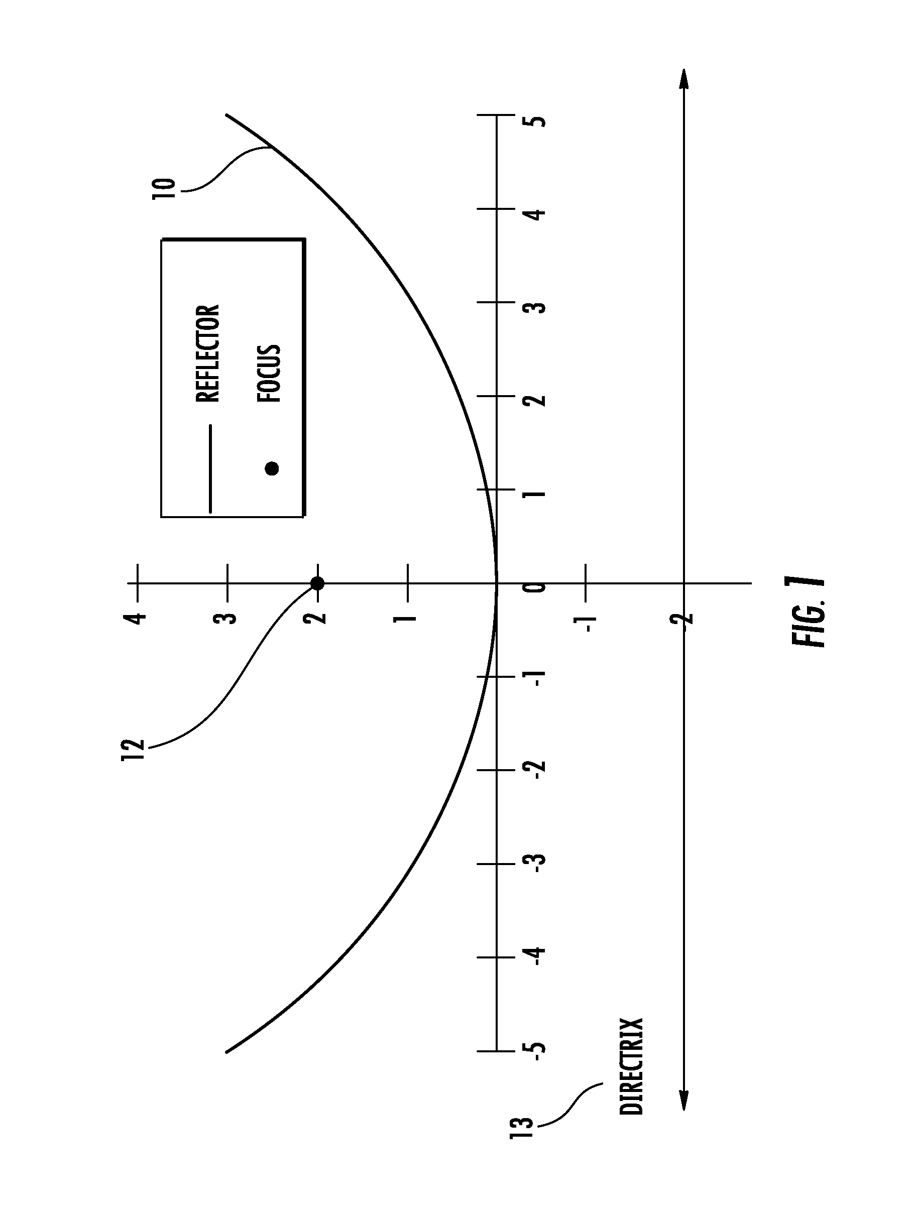
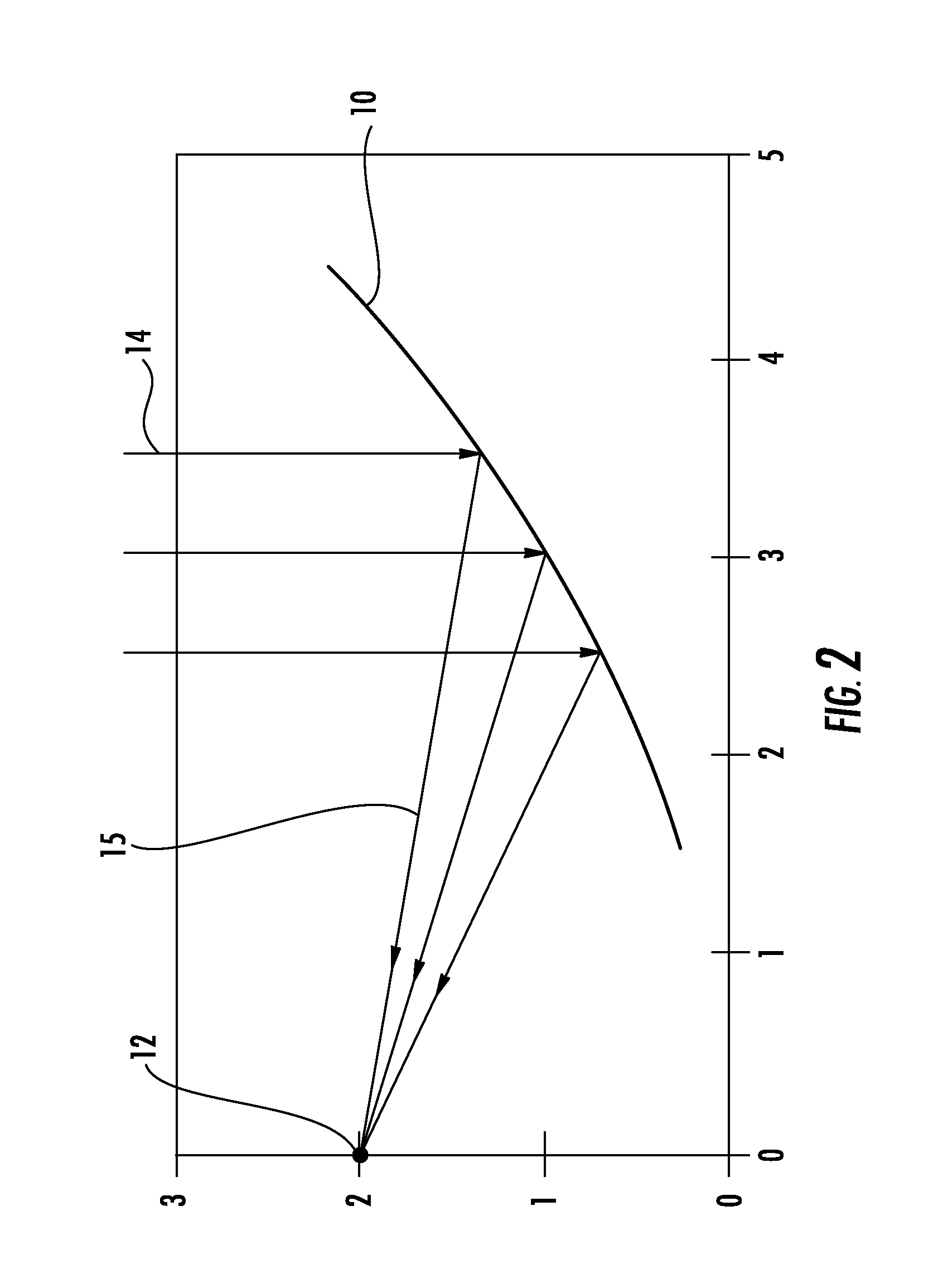
[0035]As commonly known and understood in the art, parabolic solar concentrators use mirrored surfaces curved in a parabolic shape to focus sunlight onto the mathematic...


PUM


Abstract

A solar collector system is provided that comprises an absorber tube, a primary reflector, and a secondary reflector. In certain embodiments, the primary and secondary reflectors are positioned on opposing sides of the absorber tube, such that their respective focal points converge upon a longitudinal axis of the absorber tube. The secondary reflector may be configured with a substantially transparent surface facing away from the absorber tube, so as to permit passage of light beams there-through. Opposing surfaces of the secondary and primary reflectors, namely those facing substantially toward the absorber tube contain a reflective coating thereon to facilitate redirection of light beams toward the absorber tube. The solar collector system includes in certain embodiments a frame assembly, whereby the primary reflector, the secondary reflector, and the absorber tube are all configured to unitarily rotate about a common pivot axis defined by at least a portion of the frame assembly.

Description

CROSS-REFERENCE TO RELATED APPLICATIONS[0001]This application claims priority to and the benefit of both U.S. Provisional Application No. 61 / 548,536, entitled “Apparatuses and Methods for Providing a Secondary Reflector on a Solar Collector System” and filed Oct. 18, 2011, and U.S. Provisional Application No. 61 / 560,590, entitled “Solar Thermal Energy Collector” and filed Nov. 16, 2011, the contents of both of which are hereby incorporated herein in their entirety.BACKGROUND[0002]1. Technical Field[0003]Embodiments of the present invention relate generally to solar concentrators and solar collector systems. More particularly, the various embodiments provide a solar concentrator that uses a secondary parabolic reflector assembly in conjunction with an absorber tube and a primary parabolic trough assembly to minimize the number of reflected solar rays that are never collected by the absorber tube.[0004]2. Description of Related Art[0005]Solar concentrators and solar collector systems ...

Claims


Application Information

Patent Timeline
IPC IPC(8): F24J2/18F24J2/54F24S23/79
CPCF24J2/18Y02E10/47F24J2/14F24J2/541F24S23/74F24S23/79F24S30/425
Inventor LU, WEI DAVID
Owner GEAR SOLAR
Why Eureka
Try Eureka