
Ladder assembly for equipment

a technology for ladders and equipment, applied in ladders, building construction, construction, etc., can solve the problems of ladders obstructing the view of operators to parts, preventing operators from safely entering the cabins of earthmoving equipment, and providing a hindrance to the operation of earthmoving equipmen

Inactive Publication Date: 2013-04-18
ACCESS INNOVATIONS GLOBAL LP
View PDF42 Cites 25 Cited by
  • Summary
  • Abstract
  • Description
  • Claims
  • Application Information

AI Technical Summary

Benefits of technology

The invention is a ladder assembly for equipment that includes a pivotally mounted ladder, an actuation mechanism, and a drive that engages a rotational actuator. This results in the ladder pivoting about the mount when the actuation mechanism is activated. The drive is preferably a linear actuator, such as a pneumatic or hydraulic ram, that causes rotation of a shaft attached to the ladder. The shaft is typically attached to a rotational member, such as a lever, pulley, gear, or cog and pinion, which in turn is attached to the linear actuator. The technical effect of this invention is to provide a more effective and efficient mechanism for lifting and positioning equipment using a ladder assembly.

Problems solved by technology

Therefore an operator cannot safely enter a cabin of the earthmoving equipment by simply climbing over the earthmoving equipment.
Unfortunately this fixed ladder often provides a hindrance to operation of the earthmoving equipment.
The ladder can obstruct the view of an operator to parts of the earthmoving equipment.
Although the earthmoving equipment is large, precision operation of the earthmoving equipment is often required and an obstructed view makes precision operation difficult.
Further, the fixed ladder can easily be destroyed during normal use of the earthmoving equipment.
In quarries and mines, there is often a lack of space to maneuver the earthmoving equipment.
This requires a replacement ladder at a substantial cost.
However, the cost of having the earthmoving equipment which is not in operation is often even higher than the replacement cost of the ladder.
Although many of the ladders provide excellent access for an operator to the cabin of the earthmoving equipment, when ladder is in the deployed position, many of the ladders still are a hindrance to operation of the earthmoving equipment when located in the storage position.
That is, the ladders still obstruct an operator's view and can be easily broken during operation of the earthmoving equipment.

Method used


Image

  • Ladder assembly for equipment
  • Ladder assembly for equipment
  • Ladder assembly for equipment

Examples


Embodiment Construction

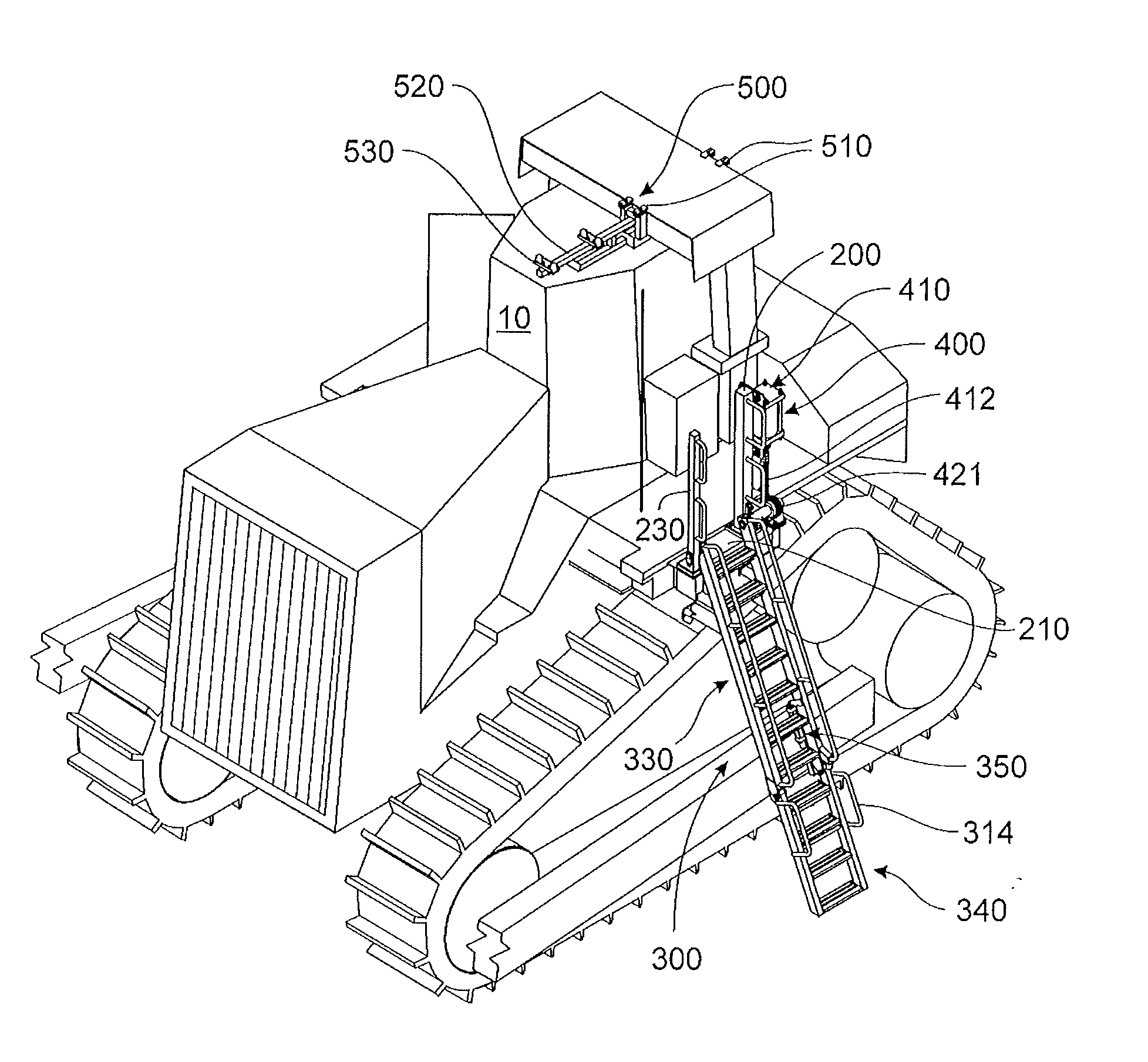
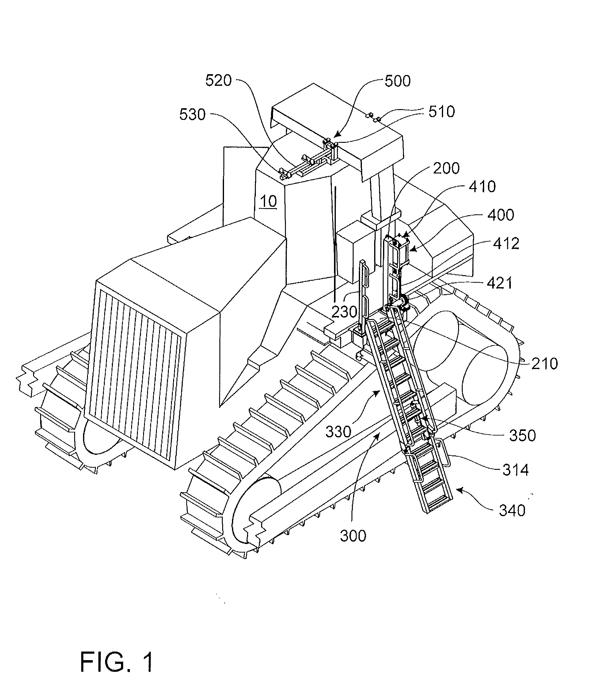
[0021]FIGS. 1 to 4 show a ladder assembly 100 mounted to a bulldozer 10 that able to be used to allow an operator to enter cabin of the bulldozer 10 as well as operate the bulldozer 10 without physical or visual impediment. The ladder assembly 100 includes a ladder 300, a pair of handrail mounts 200, an actuation mechanism 400 and a ladder support 500.

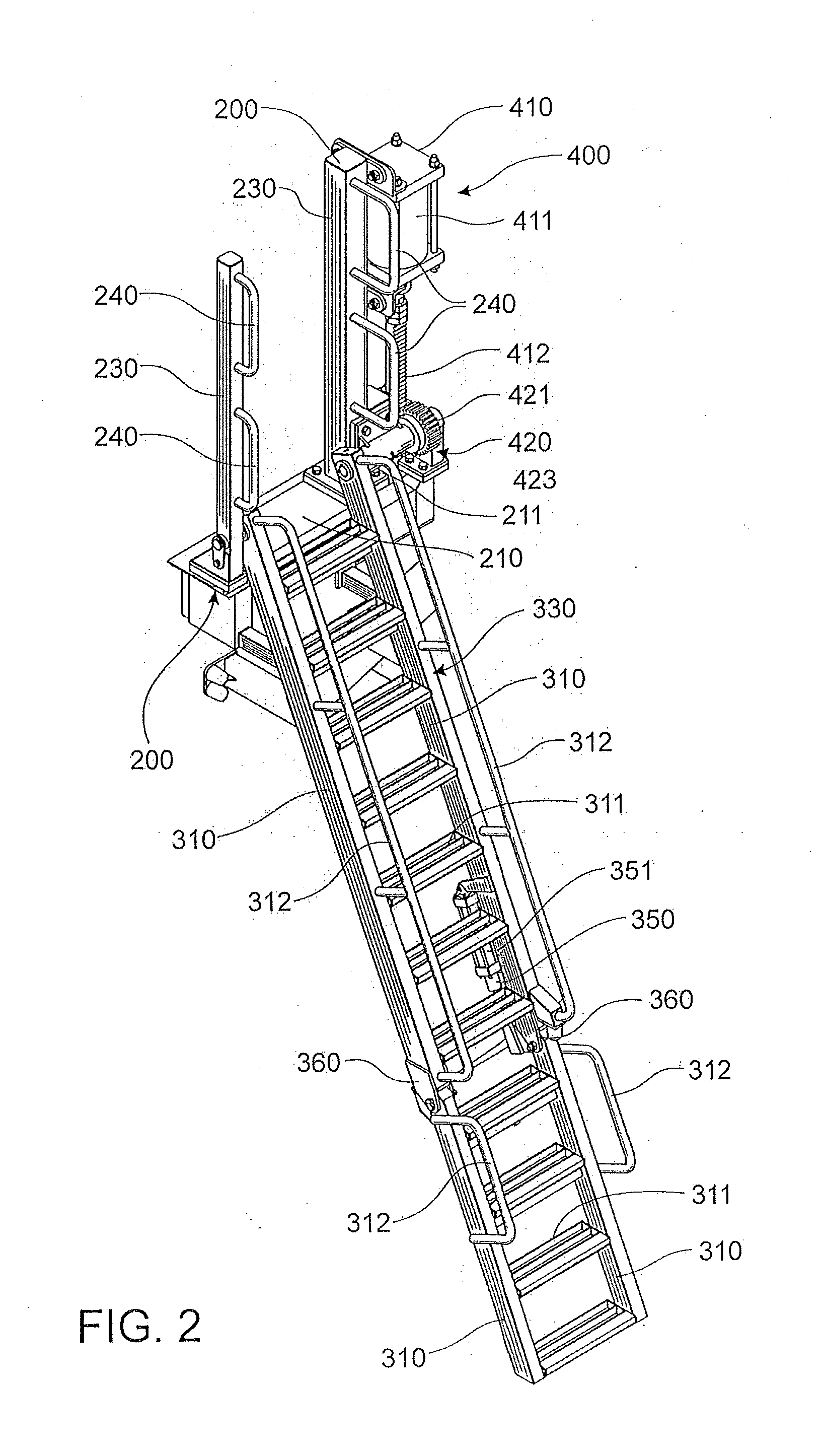
[0022]The handrail mounts 200 are used to pivotally mount the ladder 300. They are also used to assist an operator when climbing up or down the ladder 300. The handrail mounts 200 are connected to a platform 210 using fasteners 211. One of the handrails 200 is located in front of the other of the handrails 200. Each handrail mount 200 is formed from a base 220, an upwardly extending column 230 and two handrails 240.

[0023]The ladder 300 is used to enable a person to gain access to and from the bulldozer 10. The ladder 300 includes spaced apart stiles 310 which are interconnected with a series of steps 311. Railings 312 are mounted to ea...


PUM


Abstract

The invention relates to a ladder assembly for equipment, the ladder assembly comprising a ladder pivotally mounted to a mount; an actuation mechanism that includes a drive that engages a rotational actuator, the rotational actuator operatively connected to the ladder; wherein the drive causes rotation of the rotational actuator causing the ladder to pivot about the mount.

Description

FIELD OF THE INVENTION[0001]This invention relates to a ladder assembly for equipment. In particular, the invention relates to a ladder assembly for a bulldozer and therefore will be described in this context. However, it should be appreciated that ladder assembly may be used for any earthmoving equipment and vehicles such as dozers, graders, scrapers, loaders, trucks, excavators, compactors, rollers, tracked drilling units, draglines and other vehicles and units of a similar type.BACKGROUND OF THE INVENTION[0002]Earthmoving vehicles such as bulldozers, scrapers, graders and the like equipment are an integral part of many operations such as mines and quarries. Most earthmoving equipment that is used in mines and quarries is relatively large. Therefore an operator cannot safely enter a cabin of the earthmoving equipment by simply climbing over the earthmoving equipment. Accordingly, a ladder is usually required to gain access to the earthmoving equipment.[0003]Most earthmoving equipm...

Claims


Application Information

Patent Timeline
Patent Type & Authority Applications(United States)
IPC IPC(8): E06C5/02
CPCE06C5/36E06C5/04
Inventor MAGNUSSEN, MICHAEL WILLIAM
Owner ACCESS INNOVATIONS GLOBAL LP
Learn More