One-way clutch

Inactive Publication Date: 2013-04-18
NEEDLE ROLLER BEARING
View PDF8 Cites 4 Cited by
  • Summary
  • Abstract
  • Description
  • Claims
  • Application Information

AI Technical Summary

Benefits of technology

[0009]Therefore, the primary object of the present invention is to p

Problems solved by technology

Assembly is more difficult and requires more skillful workers eq

Method used


Image

  • One-way clutch
  • One-way clutch
  • One-way clutch

Examples


first embodiment

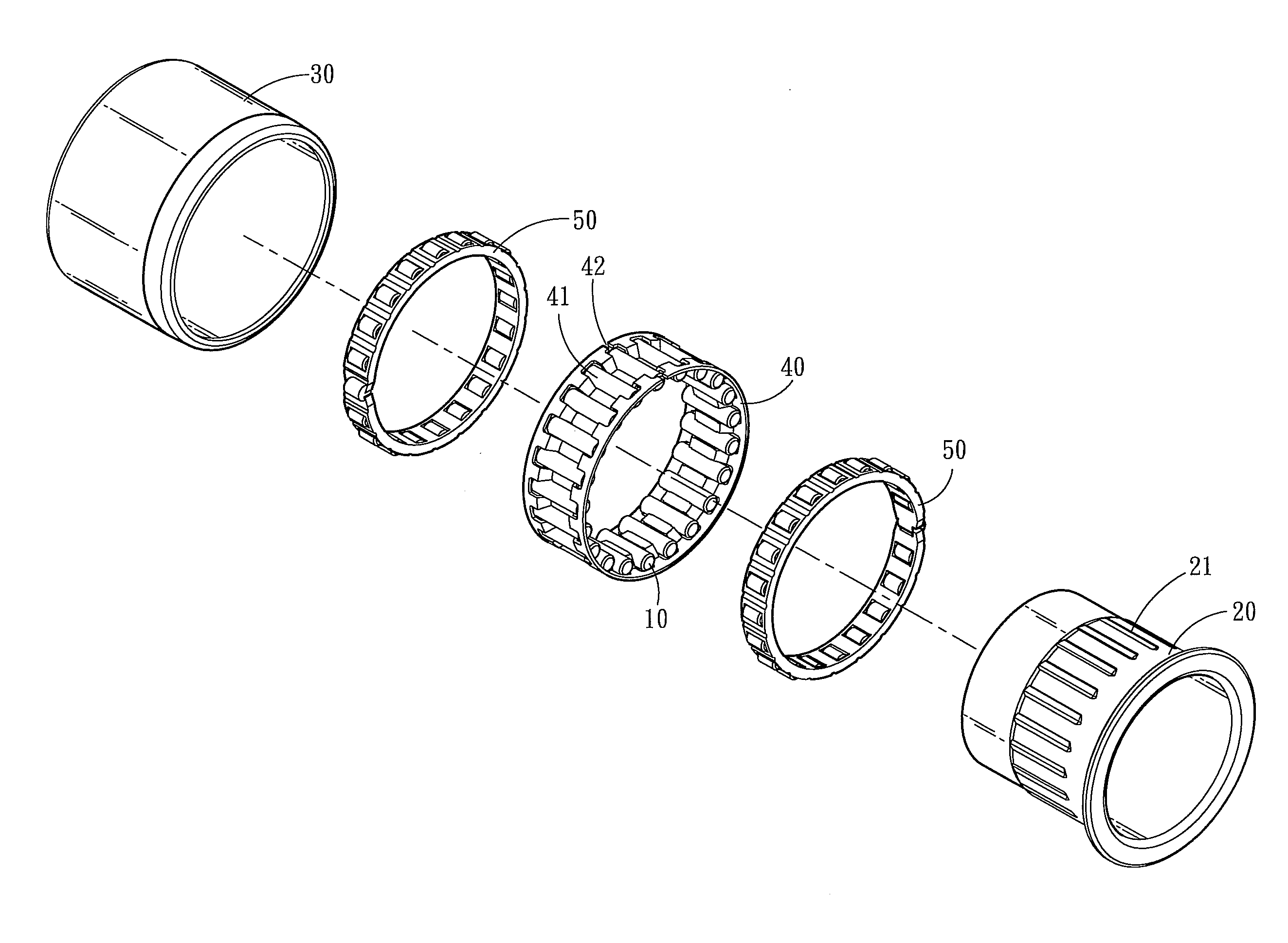
[0031]The present invention also provides two embodiments of fabrication method for the two different structures set forth above. In the first embodiment, when the first collar 20 is held inside the second collar 30, the circular holding frame 40 has an outer diameter slightly greater than the inner diameter of the second collar 30 before assembly; during assembly, the circular holding frame 40 is shrunk to a smaller dimension to be squeezed into the second collar 30; then the circular holding frame 40 is expanded through elasticity to tightly contact with the second collar 30.

second embodiment

[0032]In the second embodiment, the first collar 20A is coupled on the outer side of the second collar 30A, and the circular holding frame 40A is formed at an inner diameter slightly smaller than the outer diameter of the second collar 30A before assembly. During assembly, the circular holding frame 40A is expanded to a greater dimension to be coupled on the outer side of the second collar 30A, and then the circular holding frame 40A shrinks elastically to tightly contact with the second collar 30A.

[0033]Please refer to FIGS. 8 and 9 for the invention in operating conditions. First, the second collar 30 is driven to rotate relative to the first collar 20 towards the higher portions of the inclined bottom surfaces 22; the second collar 30 drives the circular holding frame 40 rotating via the friction force and pushes the rollers 10 to contact with the higher portions of the inclined bottom surfaces 22, thereby the rollers 10 are in contact with the first and second collars 20 and 30 ...


PUM


Abstract

A one-way clutch includes multiple rollers, a first collar and a second collar that are coupled together to form relative rotation between them, and a circular holding frame. The first collar has multiple cavities each having an inclined bottom surface. The circular holding frame has multiple slots corresponding to the rollers and exposing the cavities. The second collar is rotated to drive the circular holding frame rotating through friction force so that each roller is pushed to contact a higher portion of the inclined bottom surface and also the second collar drives the first collar rotating via pushing of the rollers. When rotational speed of the first collar is greater than that of the second collar, each roller enters a lower portion of the inclined bottom surface and separates from the second collar without transmitting torsional force between the second collar and first collar.

Description

FIELD OF THE INVENTION[0001]The present invention relates to a one-way clutch and particularly to a structure of a one-way clutch.BACKGROUND OF THE INVENTION[0002]Please refer to FIGS. 1 and 2, a conventional one-way clutch includes a first collar 1, a second collar 2, a circular holding frame 3, a plurality of rollers 4 and a plurality of elastic elements 5 at a number corresponding to the rollers 4. The first collar 1 is coupled with the second collar 2 to form relative rotation with each other. The first collar 1 may be held inside the second collar 2, and has a plurality of cavities 6 at a number corresponding to the rollers 4. The circular holding frame 3 is located between the first collar 1 and second collar 2 and fixedly located on the first collar 1, and also has a plurality of slots 7 at a number corresponding to the rollers 4 and exposing the cavities 6. Each cavity 6 has an inclined bottom surface 8 with a lower portion spaced from the second collar 2 at a distance great...

Claims


Application Information

Patent Timeline
IPC IPC(8): F16D41/067
CPCF16D41/067
Inventor HSUEH, LI-YU
Owner NEEDLE ROLLER BEARING
Why Eureka
Try Eureka