Vehicle mounting assembly for a fuel supply

a technology for fuel supply and vehicle mounting, which is applied in the directions of transportation and packaging, transportation items, packaging, etc., can solve the problems of reducing the adverse effects of control mechanisms, increasing the fuel consumption and wear of operative components, and potentially harmful to the operation of the vehicle engin

Inactive Publication Date: 2013-04-18
GASEOUS FUEL SYST
View PDF7 Cites 32 Cited by
  • Summary
  • Abstract
  • Description
  • Claims
  • Application Information

AI Technical Summary

Benefits of technology

[0020]Additional features of the housing include a stabilizing assembly disposed on the interior thereof in confronting relation to the one or more fuel tanks defining the containment structure. As such, the stabilizing assembly comprises at least one but more practically a plurality of stabilizing members disposed in spaced relation to one another and collectively extending along and confronting a length of the containment structure. Moreover, the one or more stabilizing members include a recessed configuration which at least partially corresponds to the exterior dimension and configuration of the fuel tanks. As a result, a confronting relation between the stabilizing members and the fuel tank(s) serve to restrict movement of the fuel tanks within the interior of the housing during travel or operation of the vehicle, whether the housing and fuel tanks are in the aforementioned first or second orientations.
[0021]In addition to the above, the mounting assembly of one or more preferred embodiments of

Problems solved by technology

These attempts serve to diminish adverse effects of control mechanisms which may be potentially harmful to the vehicle engine operation as well as being uneconomical.
Typical adverse effects include increased fuel consumption and wear on operative components.
As a result, many diesel engines associated with heavy duty and off-road vehicles are commonly operated at maximum or ne

Method used


Image

  • Vehicle mounting assembly for a fuel supply
  • Vehicle mounting assembly for a fuel supply
  • Vehicle mounting assembly for a fuel supply

Examples


Embodiment Construction

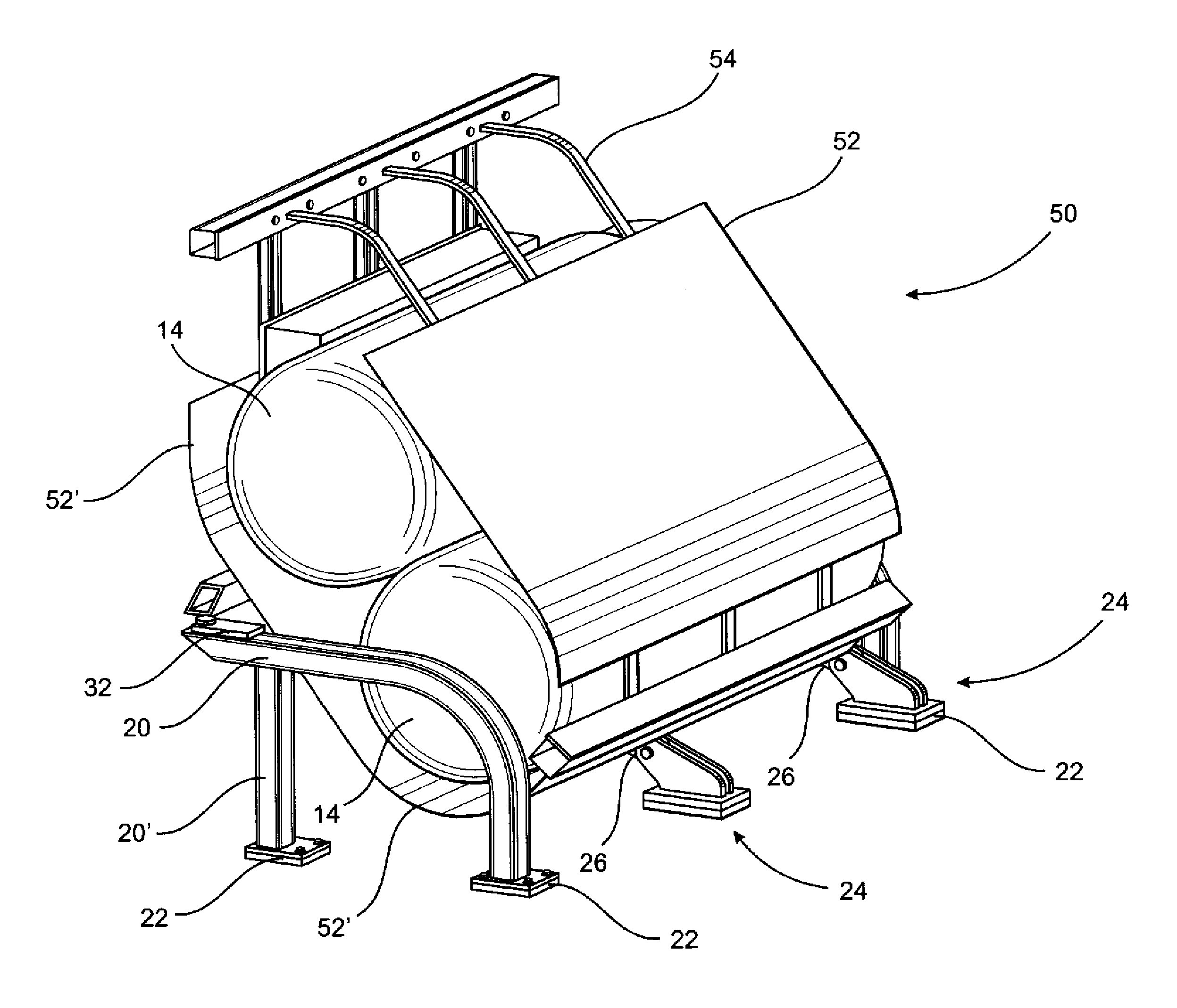
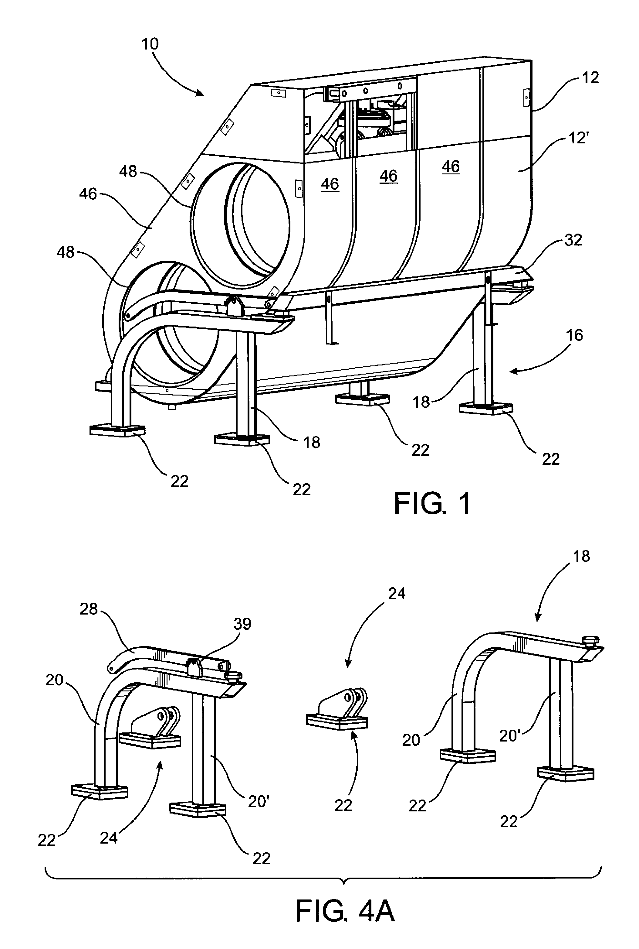
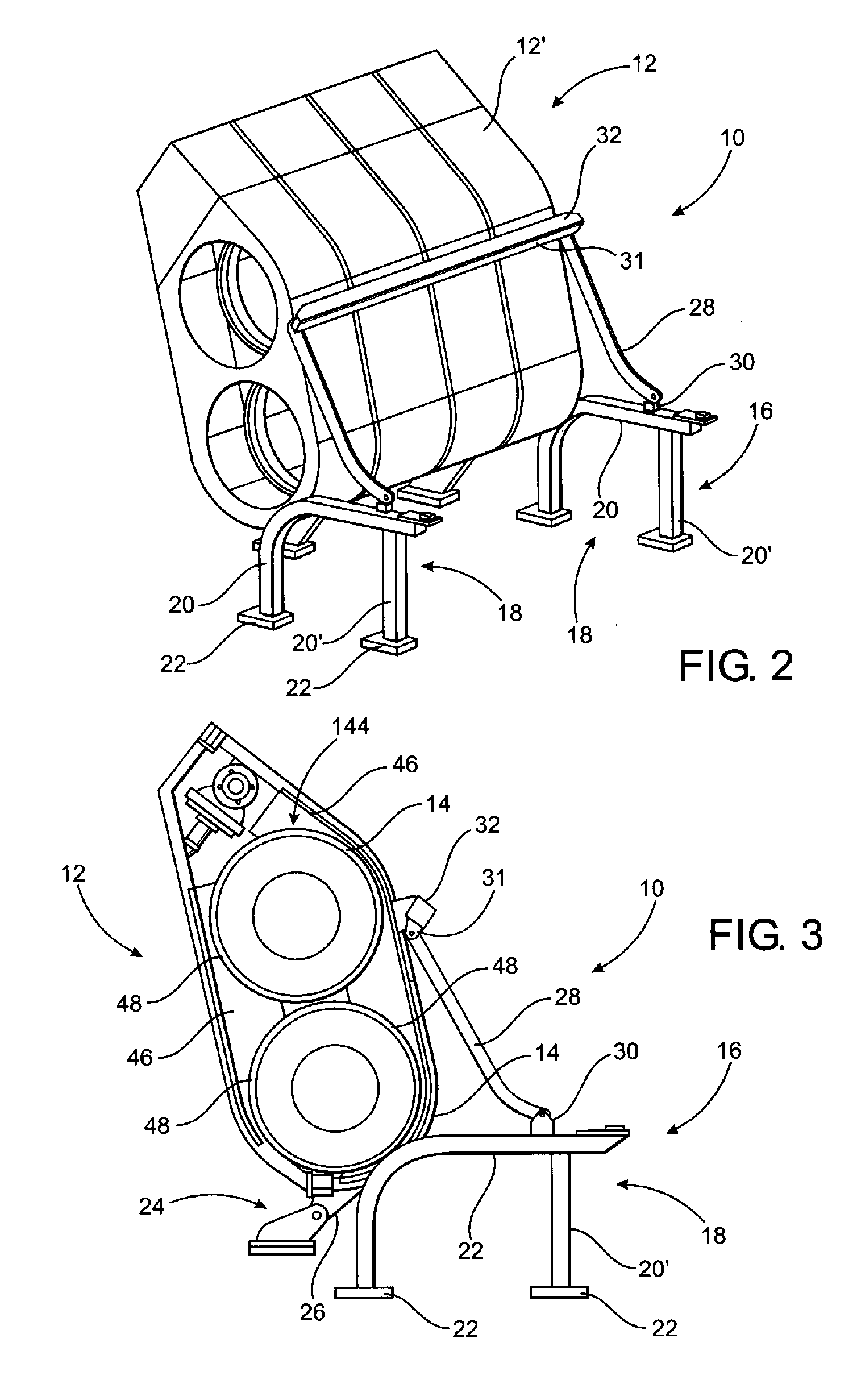
[0040]As shown in the accompanying drawings, the present invention is directed to a mounting assembly generally indicated as 10 for supporting and movably interconnecting a housing generally indicated as 12 to a vehicle. The mounting assembly 10 is specifically, but not exclusively, intended for use on a heavy duty “mine haul” vehicle, bulldozer or other vehicle especially of the type used in heavy duty commercial and / or working environments. The housing 12 is structured to include a fuel supply disposed within a containment structure, wherein the containment structure comprises at least one but in certain practical applications, a plurality of at least two fuel tanks 14. However, it is emphasized that more than two fuel tanks can be included in the housing 12 of the mounting assembly 10. As also represented, the housing 12 is supported and interconnected to the vehicle by means of a base assembly, generally indicated as 16. With primary reference to FIGS. 1-4B, the base 16 includes...


PUM


Abstract

A mounting assembly for supporting a fuel supply on a vehicle, which is specifically adapted for the operable support and positioning of an auxiliary fuel supply. The vehicle with which the mounting assembly is utilized may vary significantly, but is primarily structured for use on mine haul vehicles, bulldozers, and other heavy duty commercial vehicles, wherein the operation thereof is significantly benefited or enhanced through the provision of an auxiliary, or alternate fuel supply such as, but not limited to, liquid natural gas (LNG), selectively powering the engine of the vehicle as determined by an improved electronic control system. The mounting assembly comprises a containment structure in the form of at least one fuel tank and a housing is structured to enclose the fuel tank. A base supports both the housing and the fuel tank and a shield assembly, associated with the housing protect the fuel tank against impact in the working environment of the vehicle on which the fuel supply and containment structure are disposed.

Description

BACKGROUND OF THE INVENTIONField of the Invention[0001]This invention is directed to a mounting assembly for supporting an auxiliary or primary fuel supply on a vehicle such as, but not limited to, mine haul vehicles, bulldozers, and other heavy duty commercial vehicles. As such, the operation of the vehicle with which the mounting assembly is used may be significantly enhanced through the provision of an auxiliary or selectively alternate fuel supply, dependent at least in part on the operating mode and characteristics of the vehicle. Moreover, the alternate fuel may be liquid natural gas (LNG).DESCRIPTION OF THE RELATED ART[0002]Mine haul trucks are off-highway, two axle, rigid dump trucks, specifically engineered for use in high production mining and heavy duty construction environments. As such, haul truck capacities typically range from 50 short tons (45 tons) to 400 short tons (363 tons). In addition, the largest and highest payload capacity of such haul trucks are referred to...

Claims


Application Information

Patent Timeline
IPC IPC(8): B65D88/12
CPCB60K2015/03157B65D90/146B60Y2200/142B60K15/07
Inventor GREEN, JASON E.
Owner GASEOUS FUEL SYST
Why Eureka
Try Eureka