Tool attachment

Active Publication Date: 2013-04-18
ROBERT BOSCH GMBH
View PDF10 Cites 208 Cited by
  • Summary
  • Abstract
  • Description
  • Claims
  • Application Information

AI Technical Summary

Benefits of technology

[0005]It is an object of this invention, therefore, to make a n

Problems solved by technology

The disadvantage of the related art is believed to be that in each instance, the user needs both hands to lock such a tool attachment on a corresponding hand-held machine tool, one hand

Method used


Image

  • Tool attachment
  • Tool attachment
  • Tool attachment

Examples


Embodiment Construction

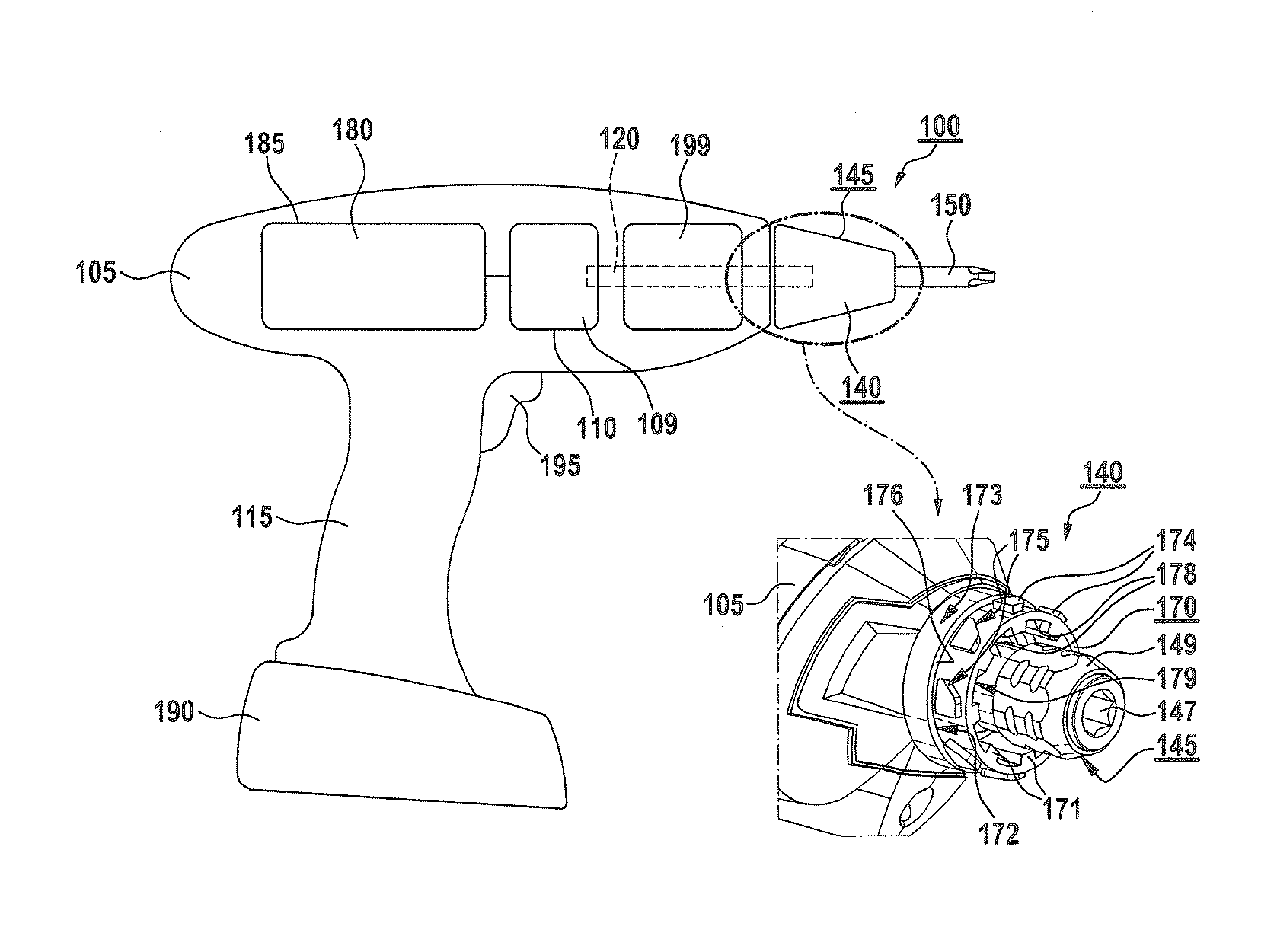
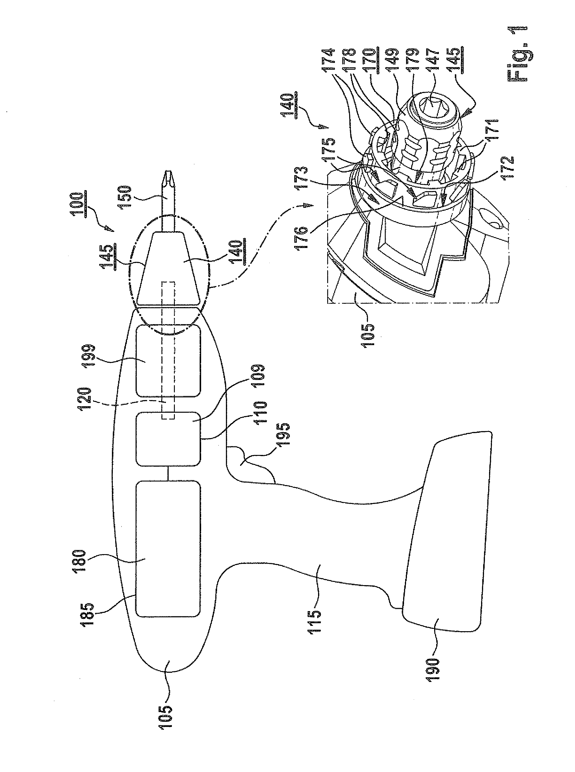
[0030]FIG. 1 shows an exemplary hand-held machine tool 100 which has a tool housing 105 having a grip 115. According to one specific embodiment, hand-held machine tool 100 is connectable mechanically and electrically to a battery pack 190 for the cordless power supply. By way of example, hand-held machine tool 100 in FIG. 1 is in the form of a cordless drill / driver. However, it is stressed that the exemplary embodiments and / or exemplary methods of the present invention are not limited to cordless drill / drivers, but rather may be used for various hand-held machine tools in which a tool is set in rotation, regardless of whether the hand-held machine tool is operable dependent on the power grid or cordlessly with battery pack 190, e.g., for a screwdriver or cordless screwdriver, an impact driver or cordless impact driver, an impact drill or a cordless impact drill, etc.

[0031]Disposed in tool housing 105 are an electric drive motor 180, supplied with current by battery pack 190, and a g...


PUM

PropertyMeasurementUnit
Forceaaaaaaaaaa
Elevationaaaaaaaaaa

Abstract

A tool attachment for mounting on a hand-held machine tool provided with a tool holder, the tool attachment having an output shaft and a base body at whose outer circumference a locking sleeve is disposed in a manner allowing it to rotate to release at least one assigned locking element; at the outer circumference of the base body, an anti-rotation unit is formed for the twist-proof mounting of the base body on a fastening unit assigned to the hand-held machine tool; on the anti-rotation unit and at an inner circumference of the fastening unit, complementary geometrical forms are provided which are configured to mesh with each other for the releasable, twist-proof mounting of the base body on the fastening unit.

Description


Claims


Application Information

Patent Timeline
Owner ROBERT BOSCH GMBH
Why Eureka
Try Eureka