
Turbine engine comprising a contrarotating propeller receiver supported by a structural casing attached to the intermediate housing

a technology of propeller receiver and turbine engine, which is applied in the direction of engines, mechanical equipment, sustainable transportation, etc., can solve the problems of significant play-related consumption at the end of the blade of the gas generator module, stress-causing distortion, and degrading the overall efficiency and surge margin of the turbine engin

Active Publication Date: 2013-04-25
SN DETUDE & DE CONSTR DE MOTEURS DAVIATION S N E C M A
View PDF16 Cites 24 Cited by
  • Summary
  • Abstract
  • Description
  • Claims
  • Application Information

AI Technical Summary

Benefits of technology

This patent is about a new design for a turbine engine that reduces distortions and increases efficiency. It does this by adding additional connection means that allow for relative movement between the gas generator and structural support casing, which helps to manage heat expansion and reduce stress on the gas generator. The turbine engine also includes a means for extracting and reinjecting air, which helps to reduce fuel consumption and control the thermodynamic aspects of the low-pressure compressor. Overall, this design improves the performance and efficiency of the turbine engine.

Problems solved by technology

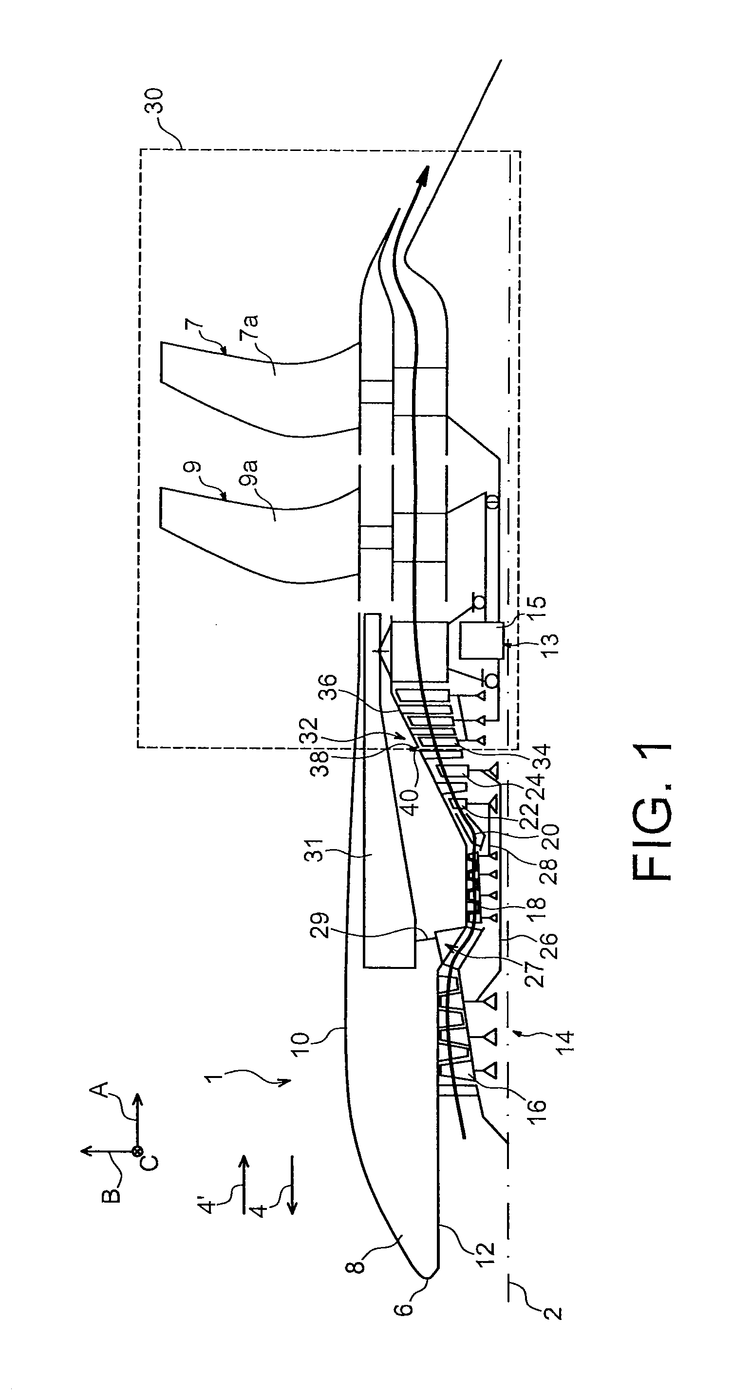
The receiver 30 is thus arranged overhanging the downstream end of the gas generator, which gives rise to stress causing distortions thereof, particularly of the outer housing thereof.
This may give rise to significant play-related consumptions at the end of gas generator module blades, particularly on the high-pressure compressor blades.
These play-related consumptions are liable to degrade the overall efficiency and surge margin of the turbine engine.

Method used


Image

  • Turbine engine comprising a contrarotating propeller receiver supported by a structural casing attached to the intermediate housing
  • Turbine engine comprising a contrarotating propeller receiver supported by a structural casing attached to the intermediate housing
  • Turbine engine comprising a contrarotating propeller receiver supported by a structural casing attached to the intermediate housing

Examples


Embodiment Construction

[0012]The aim of the invention is thus that of remedying, at least partially, the drawbacks mentioned above, in relation to embodiments of the prior art.

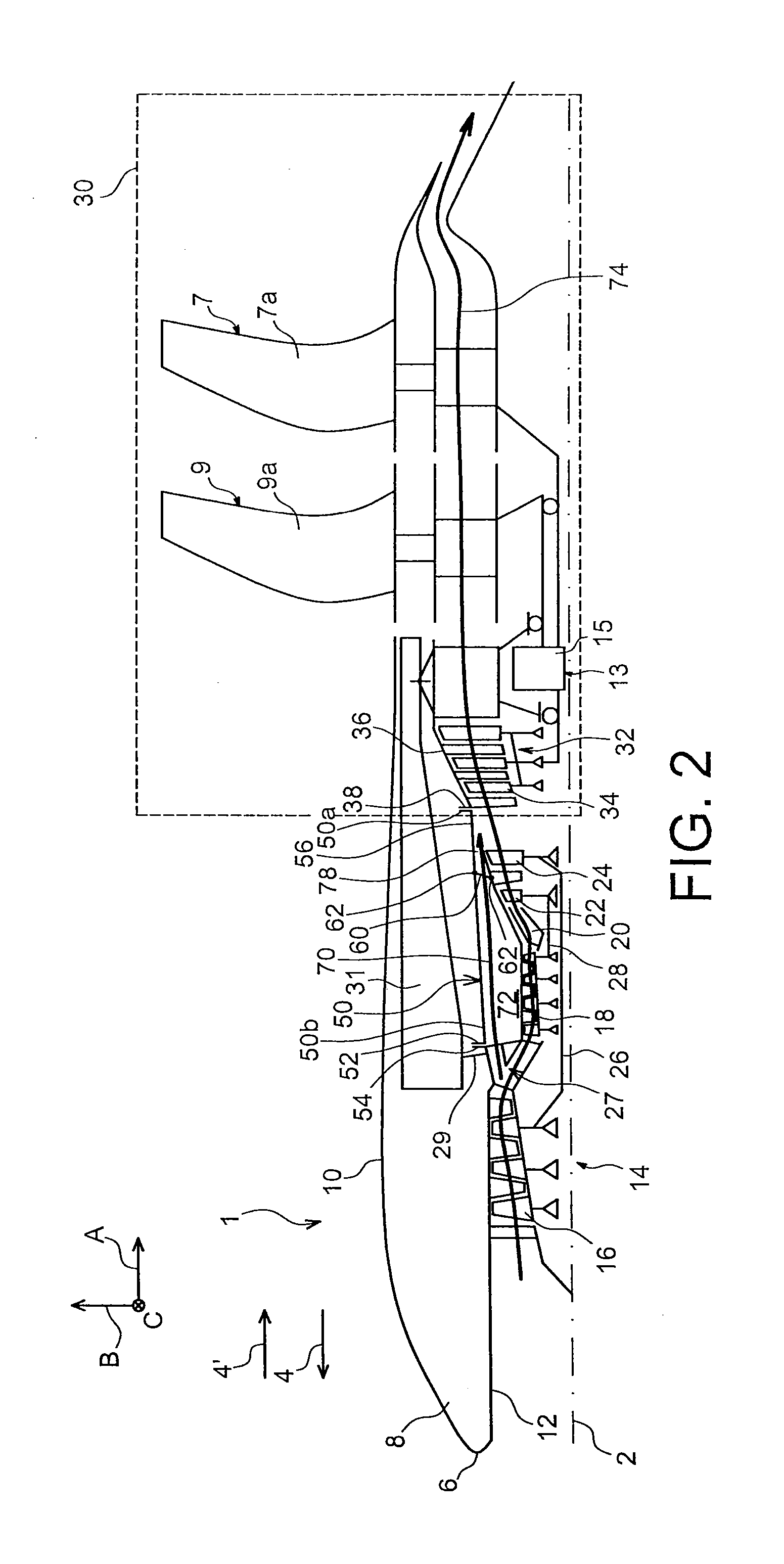
[0013]To this end, the invention relates to an aircraft turbine engine comprising a contrarotating propeller receiver and a dual-body gas generator comprising a low-pressure compressor and a high-pressure compressor separated by an intermediate housing, said gas generator being arranged upstream from said receiver.

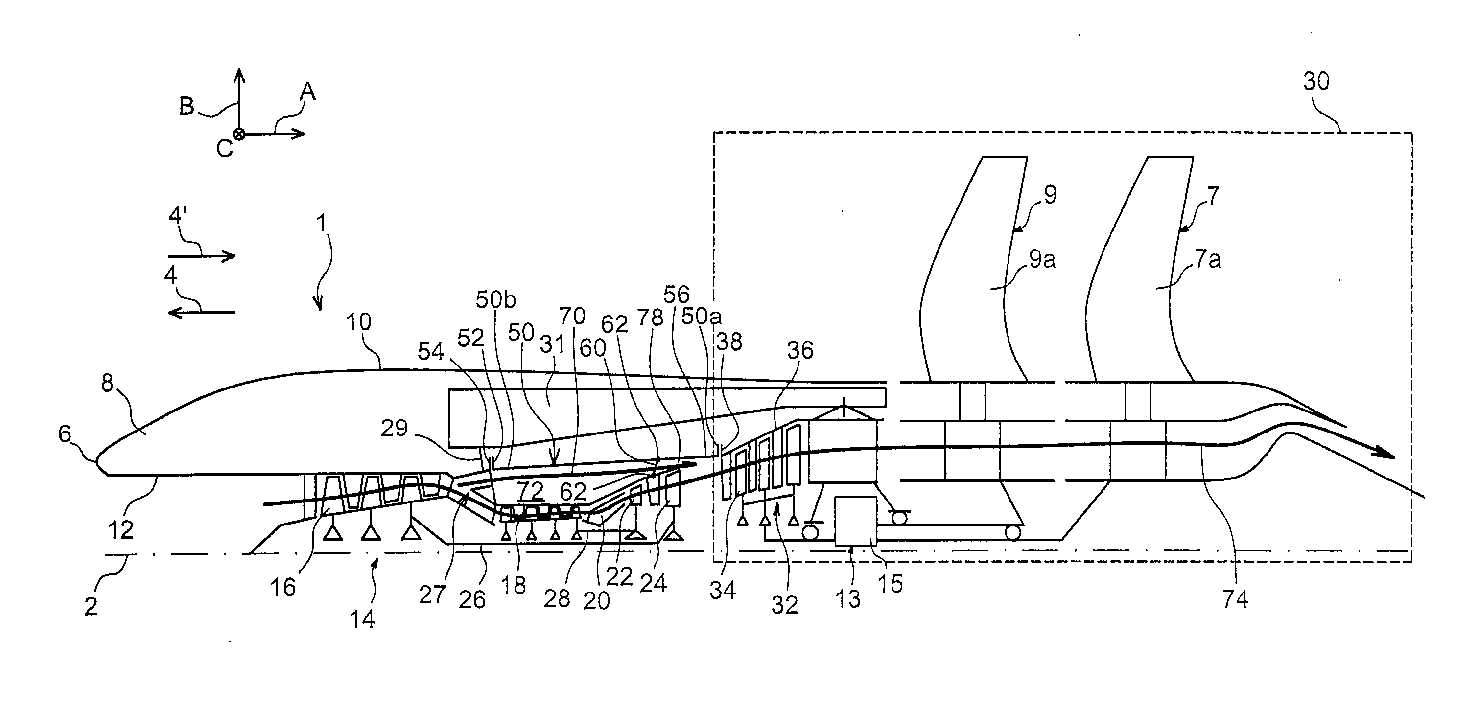
[0014]According to the invention, the turbine engine further comprises a structural casing for supporting the receiver, said casing surrounding the gas generator and having a downstream end attached to said receiver and an upstream end attached to said intermediate housing. Furthermore, it comprises additional connection means between said structural supporting casing and the gas generator, arranged between the upstream and downstream ends of the casing.

[0015]The invention is thus characterised in that it enables at least ...


PUM


Abstract

The present invention relates to an open rotor type aircraft turbine engine (1), comprising a contrarotating propeller receiver (30) and a dual-body gas generator (14) comprising a low-pressure compressor (16) and a high-pressure compressor (18) separated by an intermediate housing (27), said gas generator being arranged upstream from said receiver.According to the invention, the turbine engine further comprises a structural casing (50) for supporting the receiver (30), surrounding the gas generator (14) and having a downstream end (50a) attached to said receiver and an upstream end (50b) attached to said intermediate housing (27). Furthermore, it comprises additional connection means (60) between said structural supporting casing and the gas generator, arranged between the upstream and downstream ends (50b, 50a) of the casing.

Description

FIELD OF THE INVENTION[0001]The present invention relates to the field of aircraft turbine engines comprising a contrarotating propeller receiver arranged downstream from a gas generator.[0002]The invention particularly applies to a turbine engine having non-streamlined propellers, referred to as an open rotor turbine engine, wherein a free power turbine drives the two contrarotating propellers, directly or indirectly via a mechanical transmission device acting as a reduction gear.STATE OF THE RELATED ART[0003]FIG. 1 shows an open rotor type aircraft turbine engine 1, according to a known embodiment of the prior art, comparable to that described in the document FR 2 944 155.[0004]In this figure, direction A consists of the longitudinal direction or axial direction, parallel to the longitudinal axis 2 of the turbine engine. Direction B consists of the radial direction of the turbine engine, and direction C of the tangential direction. Furthermore, the arrow 4 represents the direction...

Claims


Application Information

Patent Timeline
Patent Type & Authority Applications(United States)
IPC IPC(8): F02C7/20
CPCF02K3/062F02K3/072Y02T50/672F05D2220/324F05D2220/325Y02T50/60F01D25/28F02C7/20
Inventor GALLET, FRANCOISGREDE, AUDREY
Owner SN DETUDE & DE CONSTR DE MOTEURS DAVIATION S N E C M A
Learn More