Printing device for containers

a printing device and container technology, applied in printing presses, rotary presses, printing, etc., can solve the problem of squeegee squeegee squeegee squeegee squeegee squeegee squeegee squeegee squeegee squeegee squeegee squeegee squeegee squeeg

Inactive Publication Date: 2013-04-25
KRONES AG
View PDF3 Cites 5 Cited by
  • Summary
  • Abstract
  • Description
  • Claims
  • Application Information

AI Technical Summary

Benefits of technology

[0007]One aspect of the present disclosure is to provide a more cost effective and simplified printing device, specifically one that does not require a retract stroke. The retract stroke of the squeegee is to be avoided.
[0008]This aspect is provided according to the present disclosure by the fact that the distance between the end of the squeegee and the squeegee-holder is variable. An squeegee-holder can also be designated as an squeegee holding device. On the one hand a predefined angle of attack can be maintained during the printing process, while also employing simple drive mechanisms to avoid an idle stroke for the squeegee-holder that occurs during oscillating motions. This results in a cost-effective system with high throughput.
[0009]Using this approach, uniform squeegee pressure can be applied onto the screen in the contact area of the squeegee with the screen, which can also be designated as a container contact device, and also permits sufficient and precisely dosed ink to be forced through the screen. The functionality is improved. The length of the squeegee varies depending on the position of the squeegee-holder on the continuous track.

Problems solved by technology

However, that system uses an oscillating squeegee that travels parallel to the container while forcing UV curing ink onto the container through a screen.
This system has the disadvantage that a retract stroke is necessary for the squeegee.

Method used


Image

  • Printing device for containers
  • Printing device for containers

Examples


Embodiment Construction

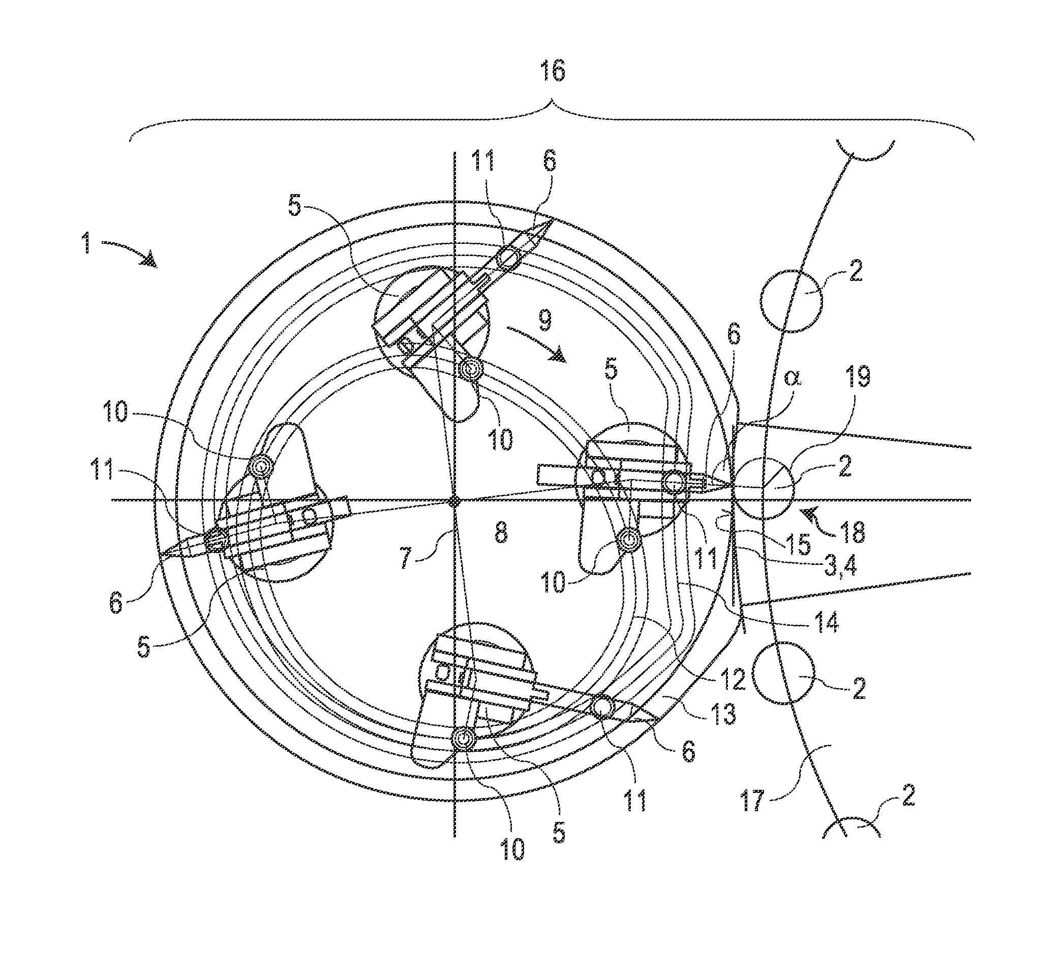
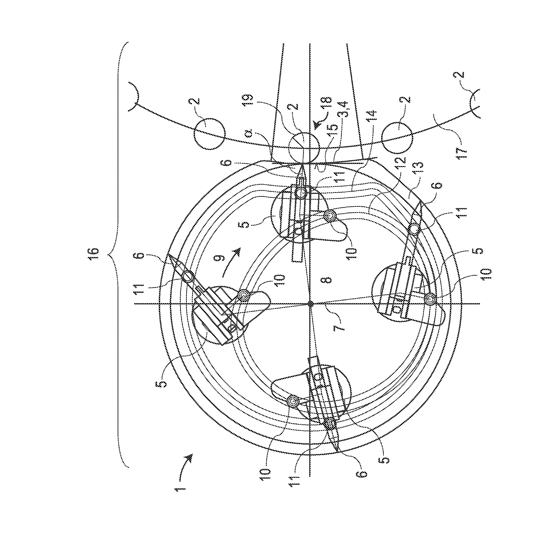
[0022]The figure represents a printing device 1 according to the present disclosure. The printing device 1 is designed to apply a fluid, such as ink or paint, onto containers 2 guided onto said printing device. Containers 2 can be configured as hollow shapes, in particular as bottles, cans, or cups. The printing device employs the screen printing principle.

[0023]The printing device 1 is equipped with a container contact device 3. The container contact device 3 is configured as a screen 4 and has mesh—not shown—through which ink can be forced. To force the ink through the screen, squeegees 6, which are attached to several squeegee-holders 5, are employed. For instance, four squeegee-holders 5 are employed that are distributed around a rotating point at a constant angle.

[0024]The squeegee-holders 5 are moved by a rotating distributor 7 around an axis of rotation 8 of the rotating distributor 7 along a circular track in the direction of arrow 9. The squeegee-holders 5 are connected to ...


PUM


Abstract

A printing device for containers, such as bottles, cans or cups, with a screen to apply a screen print onto the containers, where a squeegee holding device that is guided by a continuous track holds an squeegee in such a way that while the printed image is being applied to the container, one end of the squeegee scrapes across the screen and forces ink through the screen onto one of the containers, and where the distance between the end of the squeegee and the squeegee holding device varies. Also, a container handling device, in the manner of a bottling plant, with such a printing device and a mechanical turret designed to guide the containers to a surface of the container contact device facing away from the squeegee. Also, a method for applying ink to containers in accordance with a screen printing principle.

Description

CROSS-REFERENCE TO RELATED APPLICATION[0001]The present application claims the benefit of priority of German Application No. 102011084798.7, filed Oct. 19, 2011. The entire text of the priority application is incorporated herein by reference in its entirety.FIELD OF THE DISCLOSURE[0002]The disclosure refers to a printing device for containers, with a screen to apply a screen print onto the container, where a squeegee holder that is guided by a continuous track holds a squeegee in such a way that while the printed image is being applied to the container, one end of the squeegee scrapes across the screen and forces ink through the screen onto the container.BACKGROUND[0003]A printing device of this type is designed for hollow bodies, specifically for applying ink directly onto container(s), such as bottles, cans or cups.[0004]A device to print on the exterior container surfaces of bottles or containers is for instance known from WO 2009 / 052890 A1, although an offset print process is di...

Claims


Application Information

Patent Timeline
Patent Type & Authority Applications(United States)
IPC IPC(8): B41F17/14B41F15/44
CPCB41F15/0872B41F15/423B41F15/30
Inventor HUMELE, HEINZEDERER, ROLANDDOMEIER, BERNHARD
Owner KRONES AG
Why Eureka
Try Eureka