

Portable heat welding machine
a heat welding machine and portability technology, applied in the field of seaming machines, can solve the problems of large and very expensive, and occupying a large spa
- Summary
- Abstract
- Description
- Claims
- Application Information
AI Technical Summary
Benefits of technology
Problems solved by technology
Method used
Image

Examples
Embodiment Construction
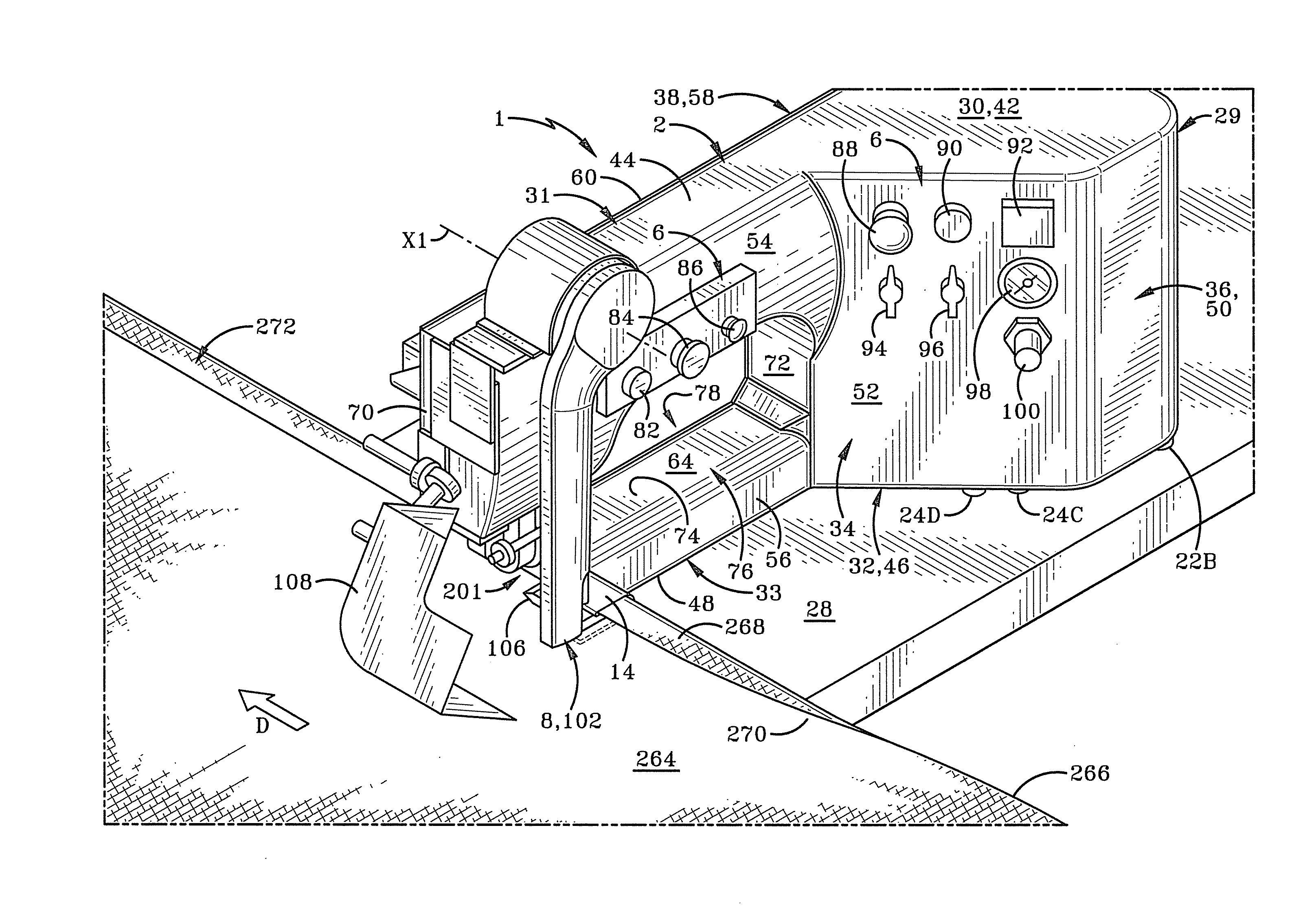
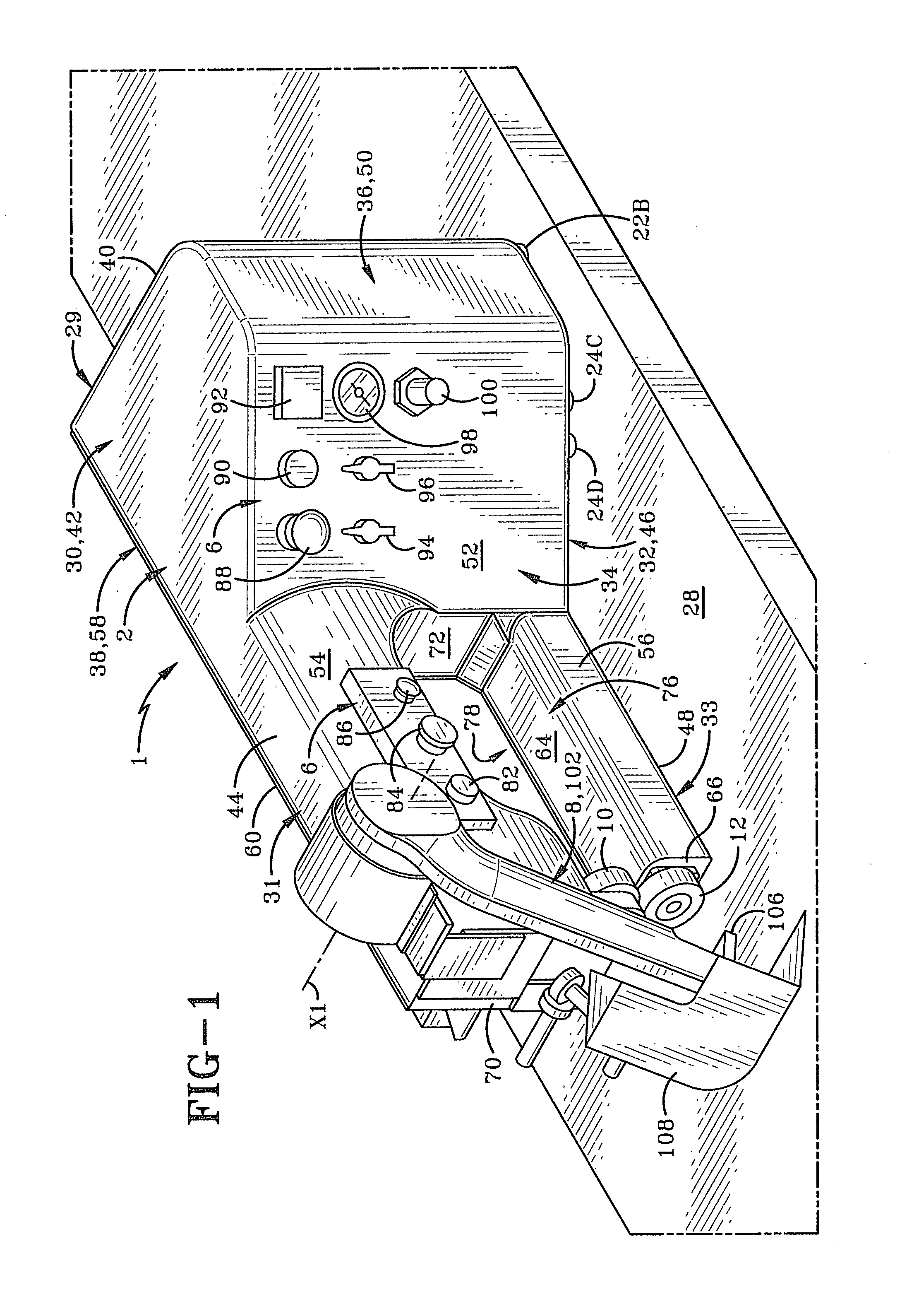
[0020]The plastic welding machine of the present invention is shown generally at 1 in FIG. 1. Machine 1 is typically configured as a generally smaller and lighter weight unit than other plastic welding machines which perform similar welding tasks. For instance, other such machines are typically in the range of about 700 pounds whereas machine 1 in the exemplary embodiment is on the order of about 105 to 110 pounds. Thus, machine 1 is generally a portable machine which may be carried by one or two persons without much difficulty. The size and configuration of machine 1 makes it highly suitable for use as a tabletop hot welding machine. In addition, machine 1 is configured to roll along a tabletop or other generally horizontal support surface as described in greater detail further below.
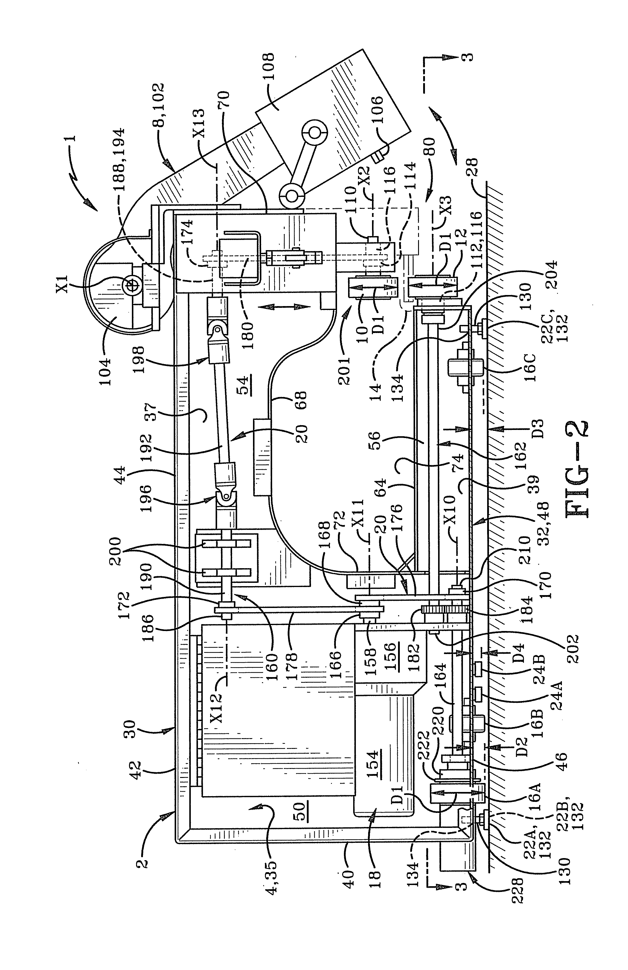
[0021]Machine 1 includes a substantially rigid frame comprising a substantially rigid housing 2 which is typically formed of metal and defines an interior chamber 4 (FIG. 2). A manually accessible cont...
PUM
| Property | Measurement | Unit |
|---|---|---|
| Flexibility | aaaaa | aaaaa |
Abstract
Description
Claims
Application Information