Rake wheel with plastic support band for tines

a technology of supporting band and rake wheel, which is applied in the field of rakes, can solve the problems of not always meeting the needs of farmers and ranchers, the hub alone cannot provide adequate support for the tines, and the raking is more difficult, so as to improve the reliability and long life of the rake tines, and minimize the wear of the tines. , the effect of quiet operation

Active Publication Date: 2013-05-02
VERMEER MFG CO
View PDF9 Cites 3 Cited by
  • Summary
  • Abstract
  • Description
  • Claims
  • Application Information

AI Technical Summary

Benefits of technology

[0019]In accordance with an aspect of the invention, a rake wheel of the present invention comprises a support band with an adaptor constructed from a material other than steel, so that the tine supporting surface at the support band is a dissimilar material than the tine to minimize the wear of the tine. According to various embodiments of the present invention, the support band is a contact ring.
[0020]In accordance with a further aspect of the invention the rake wheel of the present invention comprises a support band made from a material other than steel, so that the rigidity of the support band is reduced, providing additional cushioning of shock loads applied to the tine, which results in reduced wear and reduced noise of the assembly.
[0021]In accordance with a further aspect of the invention the rake wheel of the present invention comprises a support band, or inserts to the support band, made from a material other than steel to reduce wear on the tines.

Problems solved by technology

In the specific example of corn stover, the plants are gown in distinct rows, which results in an undulating surface, which makes raking more difficult.
Although these aforementioned prior art rakes have been in use for some time, it has been found that they do not always satisfy the needs of farmers and ranchers in part due to an inherent weakness in the common construction of the rake wheels.
However, the hub alone does not provide adequate support for the tines so the rake wheel assembly further includes an outer support band, felly, or rim typically made from a low carbon steel having a series of holes equally spaced around its circumference for receiving rake teeth or tines.
This assembly has proven to be cost effective, is commercially successful as it meets the majority of the needs for farmers and ranchers, however there are some inherent problems associated with this assembly, and a need for an improved assembly.
Although the amount of relative movement between the tine and the support band is small, it is adequate, after a high number of cycles, to cause wear of both the tine and the outer support band.
This offset results in generation of a torque load on the tine, resulting in a twisting action of the tine.
This combination of force and relative movement causes the tines and hoop holes to wear.
The practice of using similar materials exacerbates the wear.
The wear of the tine is focused in a very specific area, and has been observed to cause premature failure of the tines, which is known shortcoming of rake wheels.
In addition to the wear, the relative movement, combined with the steel-on-steel contact of the tine to the support band, causes the rake wheels to create a noticeable amount of noise.

Method used


Image

  • Rake wheel with plastic support band for tines
  • Rake wheel with plastic support band for tines
  • Rake wheel with plastic support band for tines

Examples


Embodiment Construction

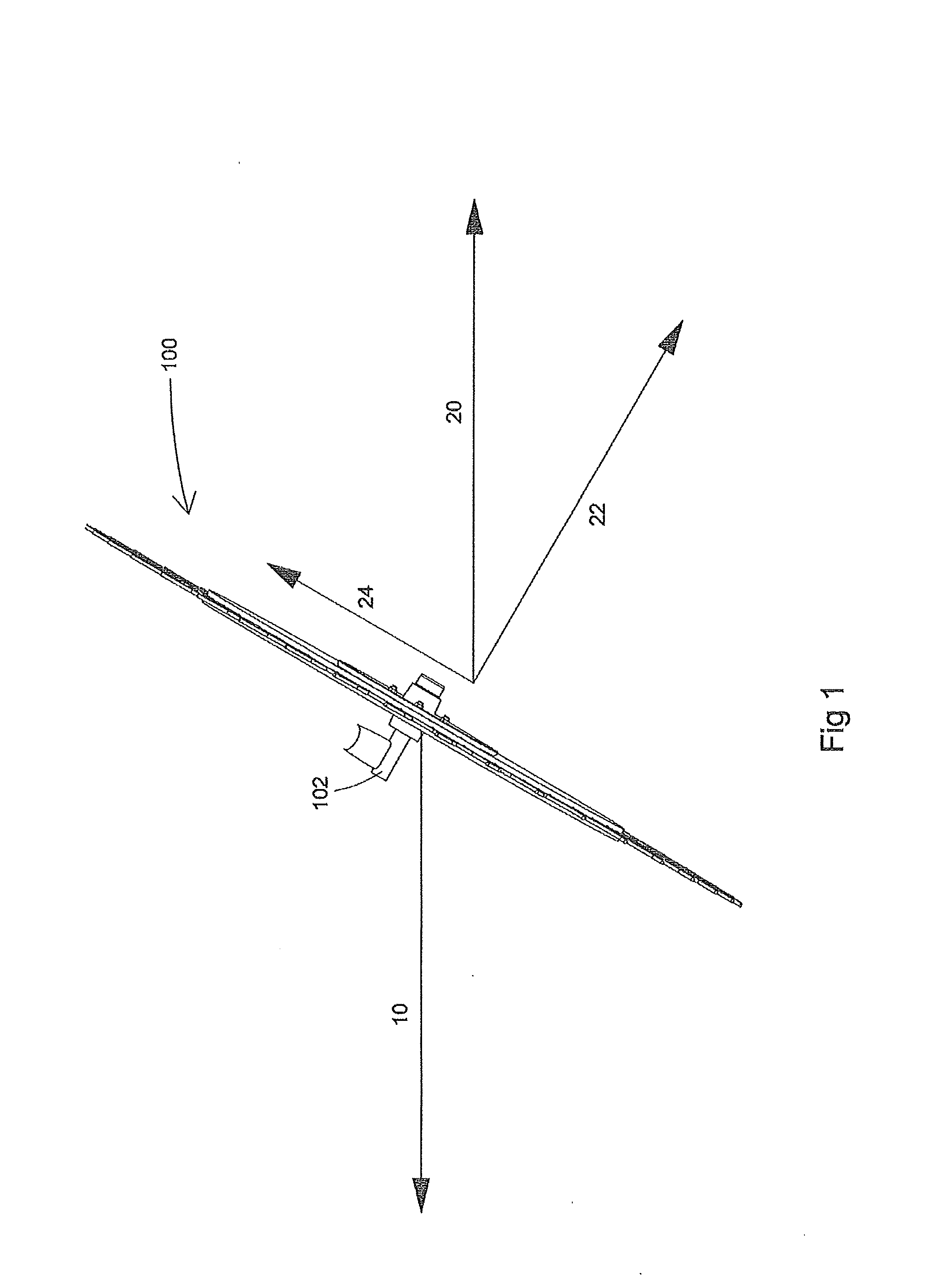
[0038]The following is a description of certain embodiments of the invention, given by way of example only and with reference to the drawings. Referring now to the drawings wherein like reference numbers designate identical or corresponding parts throughout the several views, FIG. 1 illustrates a top view of a wheel 100 mounted to spindle 102 with a vector 10 indicating a general direction of travel, and a load vector 20 showing the force that will be exerted on an individual tine. That force can be broken down into a first component 22 perpendicular to the plane of the wheel, parallel to the axis of rotation of the wheel, and a second component 24 perpendicular to the axis of rotation. The second component 24 propels the wheel, providing the force to rotate the wheel, while the first component 22 acts on the ground and / or the material that is being raked. The first component 22 is also the main force that causes the tine to deflect.

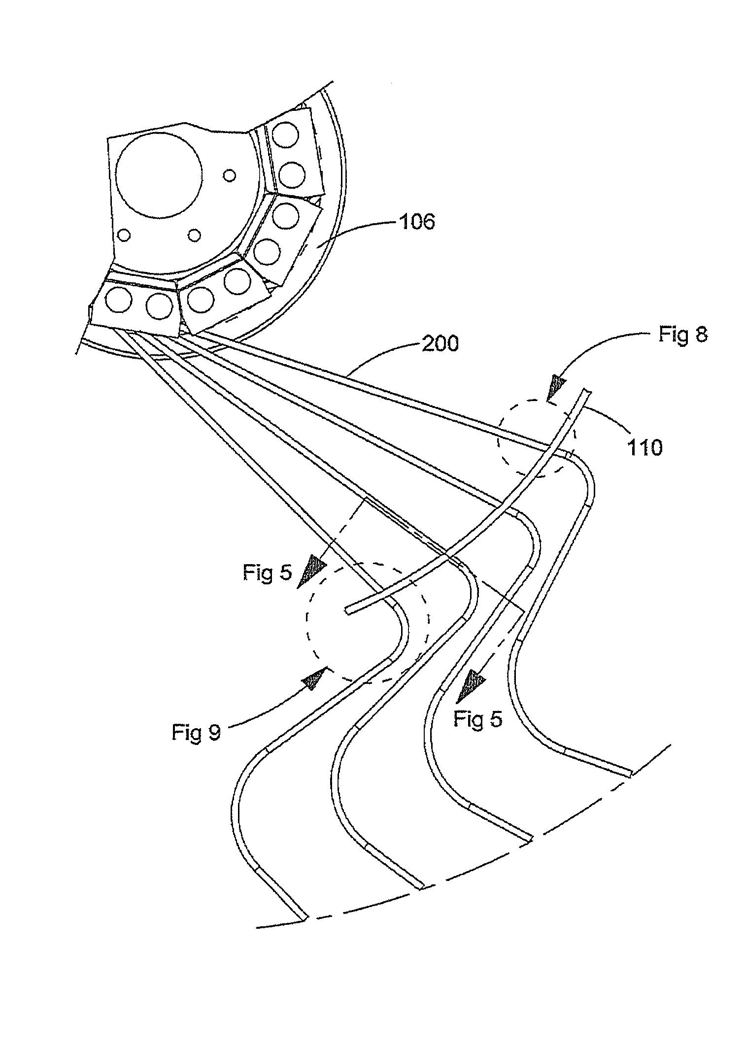
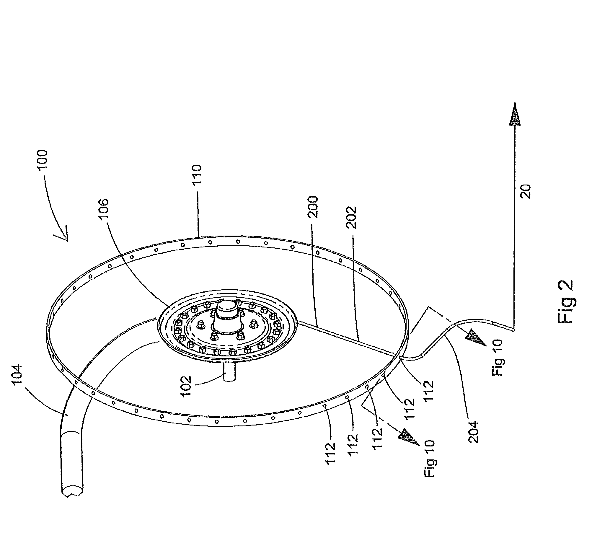
[0039]FIG. 2 illustrates one embodiment of a rake ...


PUM


Abstract

A rake wheel has a hub with tines extending outwardly from the hub. The tines extend through evenly spaced openings in a support band. At least the inner periphery of the openings through the support band are made of a material softer than the material of the tines to minimize the wear of the tines where the tines touch the inner periphery of the openings as the tines move with respect to the inner periphery of the openings during the use of the rake wheel.

Description

CROSS REFERENCE TO RELATED APPLICATIONS[0001]This application is a continuation of PCT application number PCT / PCT / NL2011 / 000052 filed on 5 Jul. 2011, which claims priority from U.S. Provisional Patent Application Ser. No. 61 / 361,587 filed 6 Jul. 2010. Both applications are hereby incorporated by reference in their entireties.BACKGROUND OF THE INVENTION[0002]1. Field of the Invention[0003]The present invention relates generally to rakes for raking hay or crop residues and more particularly to rake wheels and the construction thereof.[0004]2. Description of the Related Art[0005]Wheel rakes have been found to be an effective farm implement for raking hay, which is generally an agricultural crop grown on a relatively even surface, evenly distributed, and cut for harvest at a consistent height, or other materials like crop residues. Crop residue, like corn stover, the residue from agricultural crops left by a previous operation, typically the harvest of grain, is being harvested more now...

Claims


Application Information

Patent Timeline
Patent Type & Authority Applications(United States)
IPC IPC(8): A01D80/02A01D80/00
CPCA01D80/02A01D78/14
Inventor BENTZINGER, RUSTIN V.
Owner VERMEER MFG CO
Why Eureka
Try Eureka