
Seal member and a charging connector provided therewith

Inactive Publication Date: 2013-05-02
SUMITOMO WIRING SYST LTD
View PDF8 Cites 27 Cited by
  • Summary
  • Abstract
  • Description
  • Claims
  • Application Information

AI Technical Summary

Benefits of technology

The patent text describes a method for improving the efficiency of a fluid- or waterproof operation in cables. This is achieved by applying a heating treatment after a sealant is filled adjacent to the wires and a heat shrinkable tube is mounted on the end of the outer sheath. The restricting member, which is a cylinder that covers the entire outer peripheral surface of the cable seal portion, makes it easy to mount on the cable. The wire insertion holes in the wire seal portion are marked to indicate which ones have a different hole diameter, which helps to improve operational efficiency and avoid errors when inserting wires. Overall, this method simplifies the process of sealing cables and ensures better protection against fluid and water.

Problems solved by technology

Further, the sealant is expensive and reliably filling the clearances between the respective wires with the sealant is difficult.
Therefore sealing is not stable.

Method used


Image

  • Seal member and a charging connector provided therewith
  • Seal member and a charging connector provided therewith
  • Seal member and a charging connector provided therewith

Examples


Embodiment Construction

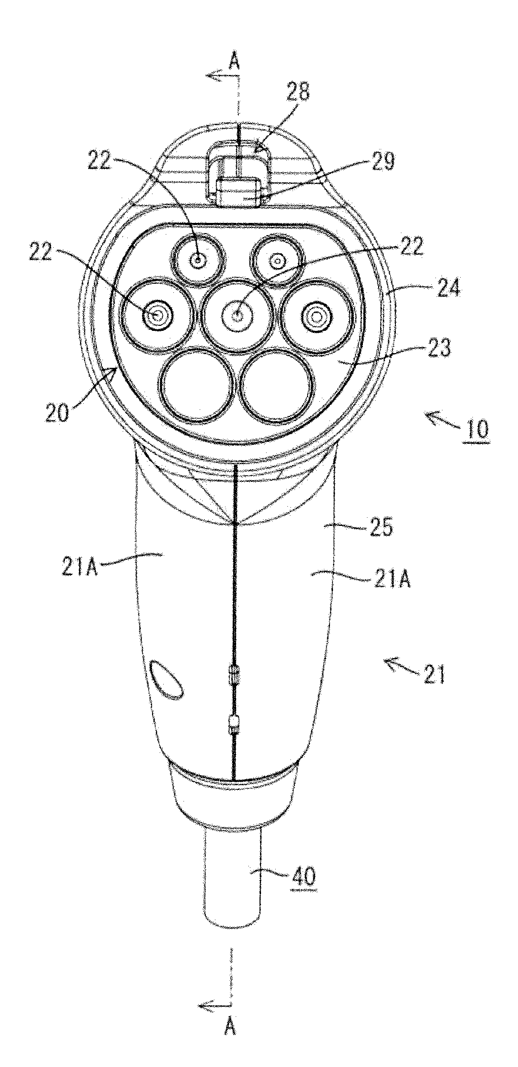
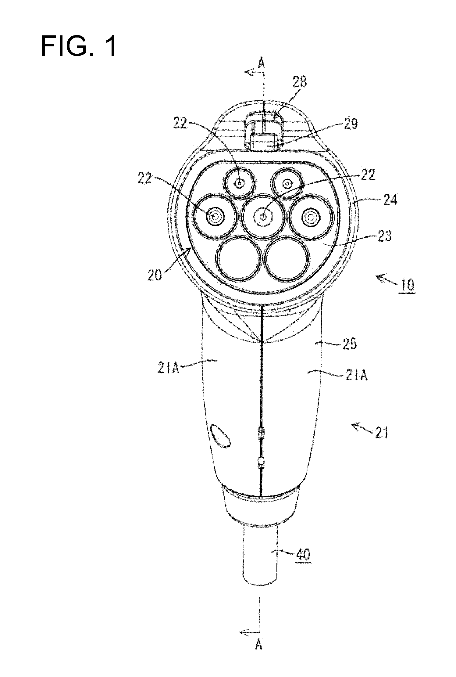
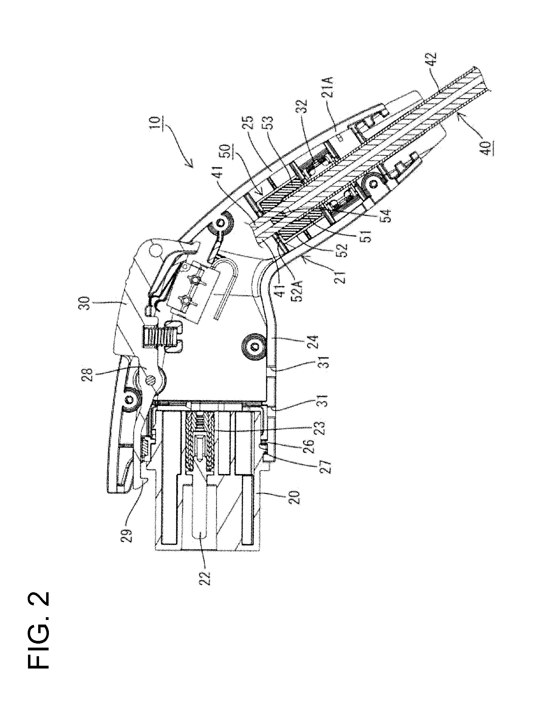
[0031]A charging connector in accordance with the invention is identified by the numeral 10 in FIGS. 1 and 2. The charging connector 10 is connected to an end of a multi-core cable 40 extending from an external power supply side and is connectable to an unillustrated vehicle side connector mounted in a vehicle.

[0032]The charging connector 10 includes a front housing 20 and a rear housing 21 both of which are made e.g. of synthetic resin. The front housing 20 can fit into an unillustrated vehicle side receptacle in the vehicle side connector, and the rear housing 21 is assembled with a rear part of the front housing 20.

[0033]The front housing 20 is substantially cylindrical and includes a terminal holding portion 23 in which male terminals 22 are held. The male terminals 22 are to be connected electrically conductively to unillustrated female terminals in the vehicle side receptacle when the front housing 20 is fit properly into the vehicle side receptacle.

[0034]The rear housing 21 c...


PUM


Abstract

A seal member (50) is to be mounted on an end of a multi-core cable (40), in which a plurality of wires (41) are bundled together and covered with an outer sheath (42). The seal member (50) is to be accommodated into a rear housing (21) of a charging connector (10) and includes a rubber plug (51) and a restricting member (52) to be externally fit on the rubber plug (51). The rubber plug (51) is formed with a cable seal portion (53) that resiliently comes into close contact with the outer peripheral surface of the outer sheath (42), and the cable seal portion (53) includes a wire seal portion (54) that individually and resiliently comes into close contact with the outer peripheral surfaces of the wires.

Description

BACKGROUND OF THE INVENTION[0001]1. Field of the Invention[0002]The invention relates to a seal member and to a charging connector provided therewith.[0003]2. Description of the Related Art[0004]U.S. Pat. No. 6,602,090 discloses a charging connector connected to ends of wires, such as signal wires and power wires. The wires are pulled into a housing of the charging connector and each wire is connected to a predetermined connecting portion in the housing.[0005]A multi-core cable is formed by bundling wires together and covering the bundled wires with an outer sheath. An end of this multi-core cable then can be pulled into a housing. Water, such as rainwater, may enter the housing and flow into the inside of the outer sheath of the multi-core cable through clearances between the respective wires and may penetrate to a power supply part through the inside of the outer sheath.[0006]Thought has been given to placing a sealant between the wires at the end of the outer sheath to close the ...

Claims


Application Information

Patent Timeline
IPC IPC(8): H02G15/04
CPCH01R13/5208H01R2201/26H01R43/005H01R13/6275
Inventor OSAWA, KIYOSHIICHIO, TOSHIFUMI
Owner SUMITOMO WIRING SYST LTD
Learn More