Debris filtering apparatus and method

a filtering apparatus and filtering technology, applied in the direction of gravity filters, loose filtering material filters, cartridge filters, etc., can solve the problems of choking, damage to equipment associated, etc., and achieve the effect of easy cleaning, service and/or repair, and low and stable profil

Inactive Publication Date: 2013-05-02
WESTERN ENERGY SERVICES PARTNERSHIP
View PDF13 Cites 6 Cited by
  • Summary
  • Abstract
  • Description
  • Claims
  • Application Information

AI Technical Summary

Benefits of technology

[0049]The apparatus may be configured so that the filter assembly or filter assemblies are oriented at any desired orientation. In some embodiments, the apparatus may be configured so that the filter assembly or filter assemblies are oriented at a substantially horizontal orientation. One advantage of orienting the filter assemblies at a substantially horizontal orientation is that the apparatus can maintain a lower and more stable profile. A second advantage of orienting the filter assemblies at a substantially horizontal orientation is that the apparatus may be relatively more easy to clean, service and / or repair because the components of the apparatus are located relatively close to the surface upon which the apparatus is resting. A third advantage of orienting the filter assemblies at a substantially horizontal orientation is that the fluid may be passed through the apparatus in a generally horizontal direction, which may coincide with the direction which the fluid is moving at the main fluid inlet. As a result, wear of components of the apparatus due to the forces required to change the direction of the fluid before the fluid is passed through the filter assemblies may possibly be reduced.

Problems solved by technology

This debris may be detrimental to equipment associated with the wellbore.
The presence of debris in a fluid which passes through a choke may plug the choke and / or cause the choke to malfunction.

Method used


Image

  • Debris filtering apparatus and method
  • Debris filtering apparatus and method
  • Debris filtering apparatus and method

Examples


Embodiment Construction

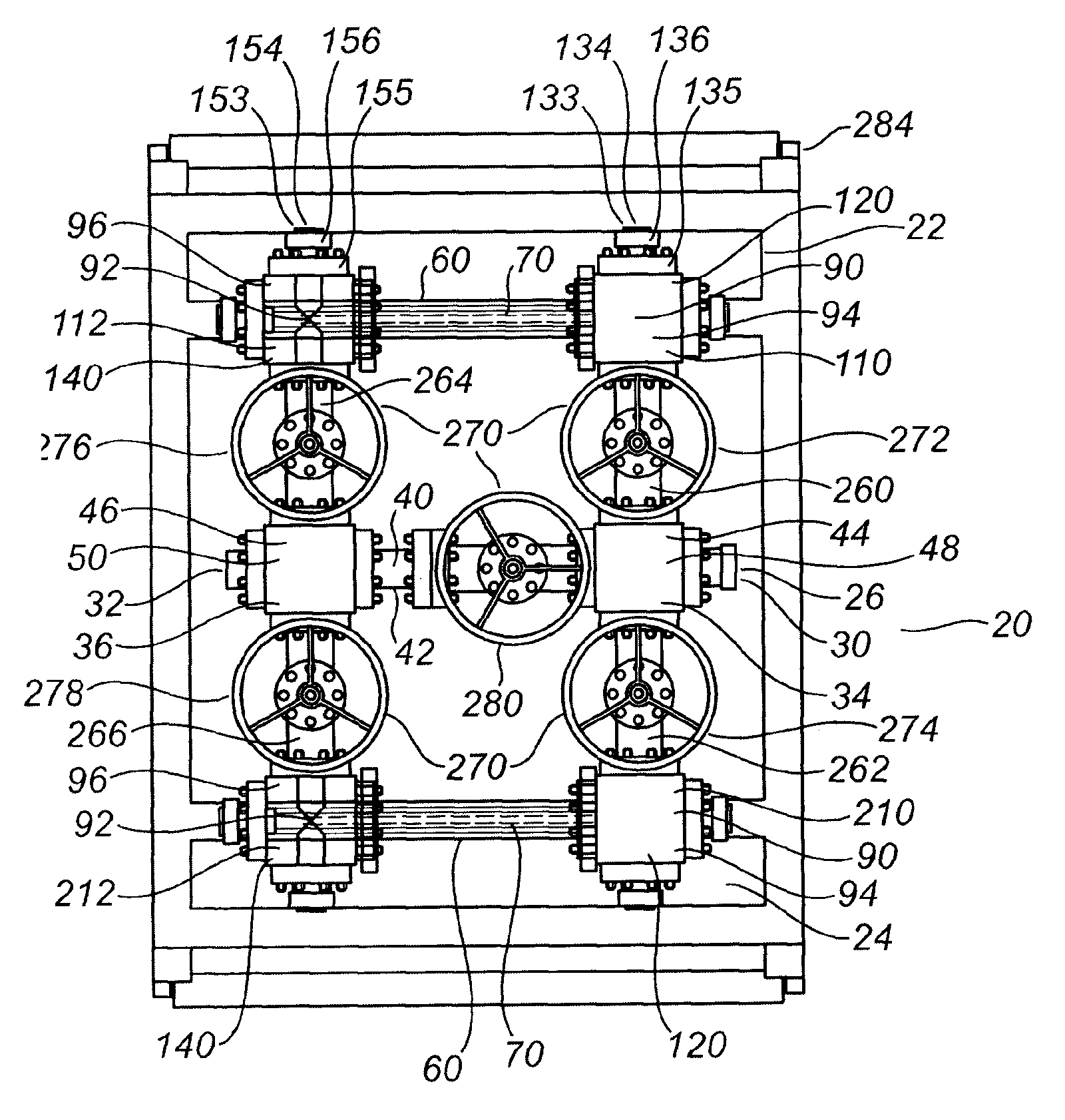
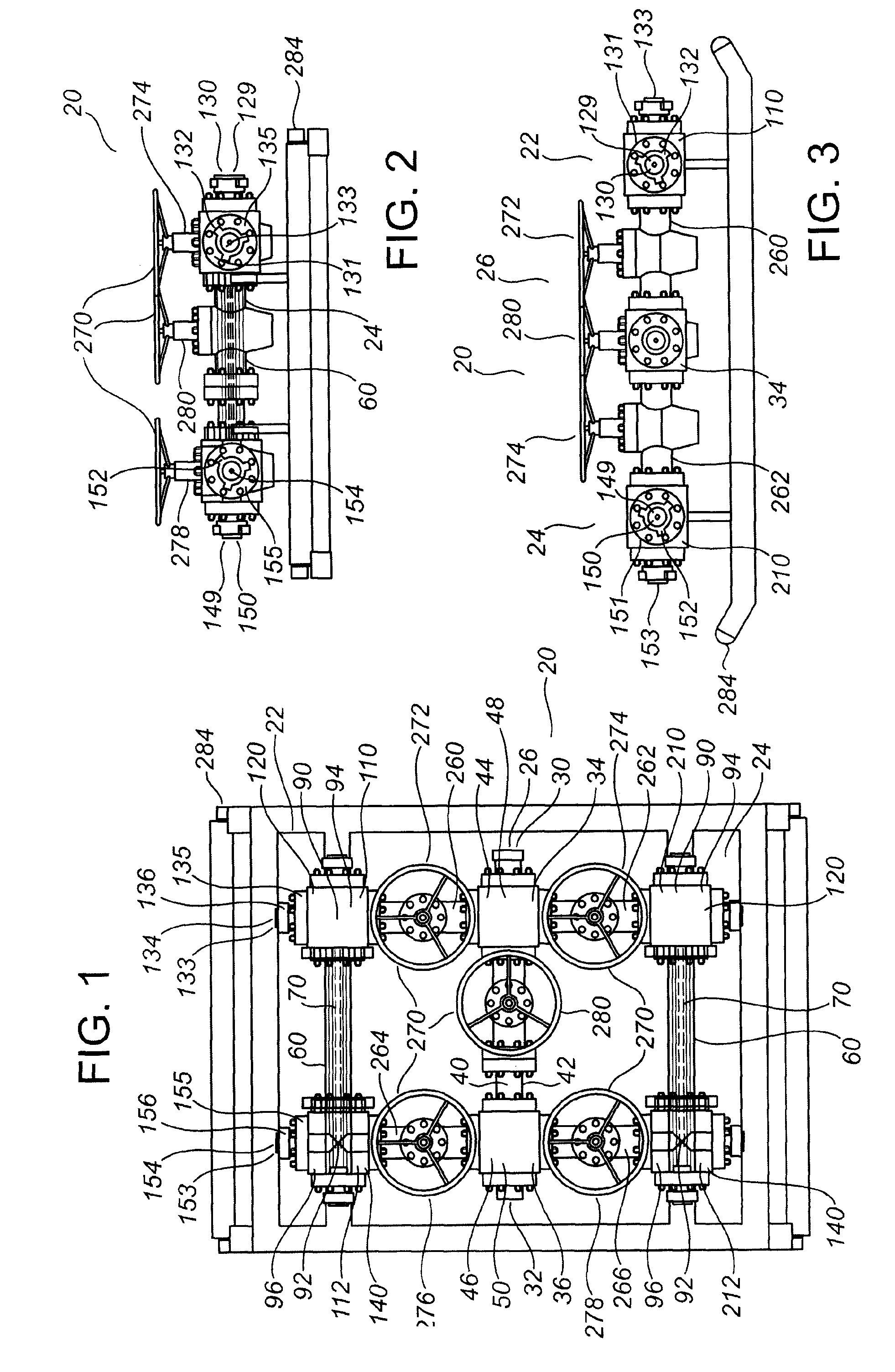
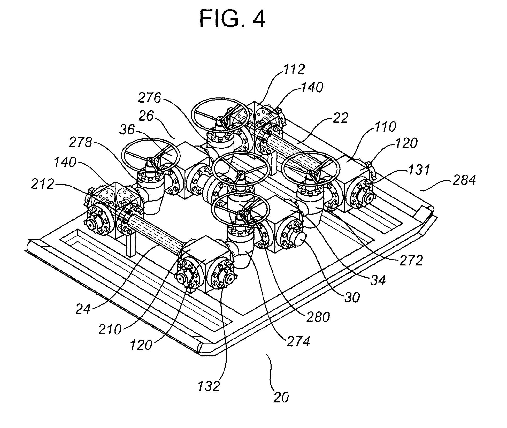
[0099]FIGS. 1-17 depict an exemplary embodiment of a debris filtering apparatus according to the invention.

[0100]Referring to FIGS. 1-4, the exemplary embodiment of the debris filtering apparatus (20) is comprised of a first filter assembly (22), a second filter assembly (24), and a bypass assembly (26). In other embodiments, the apparatus of the invention may be comprised of a single filter assembly, may be comprised of more than two filter assemblies, and may or may not be comprised of the bypass assembly (26).

[0101]The exemplary embodiment of the debris filtering apparatus (20) is further comprised of a main fluid inlet (30), a main fluid outlet (32), a main inlet manifold (34) and a main outlet manifold (36).

[0102]The bypass assembly (26) is comprised of a bypass conduit (40) which defines a bypass flowpath (42), a fluid inlet (44) which is in communication with the bypass flowpath (42), and a fluid outlet (46) which is in communication with the bypass flowpath (42).

[0103]The by...


PUM

PropertyMeasurementUnit
forcesaaaaaaaaaa
pressure dropaaaaaaaaaa
particle sizesaaaaaaaaaa

Abstract

A debris filtering apparatus and method. The apparatus includes a first filter assembly. The first filter assembly includes an outer conduit and an inner conduit received within the outer conduit. An inner conduit flow-path is defined within the inner conduit and an outer conduit flowpath is defined between the inner conduit and the outer conduit. The inner conduit includes a filter. A fluid inlet is in communication with the inner conduit flowpath and a fluid outlet is in communication with the outer conduit flowpath. The filter permits a fluid to pass between the inner conduit flowpath and the outer conduit flowpath while retaining debris within the inner conduit. The method includes passing the fluid through the first filter assembly, removing the inner conduit from within the outer conduit, removing the debris from the inner conduit, and replacing the inner conduit within the outer conduit.

Description

TECHNICAL FIELD[0001]An apparatus and a method for filtering debris from a fluid.BACKGROUND OF THE INVENTION[0002]Various fluids may be passed through a wellbore in the course of drilling, completing, testing, treating and producing fluids from the wellbore.[0003]During drilling, drilling fluid may be circulated through the wellbore. During completion, fluids associated with completing the wellbore may be passed through the wellbore. During testing, fluids associated with testing the wellbore may be passed through the wellbore. During treating, fluids associated with treating the wellbore may be passed through the wellbore. During production, hydrocarbons, water and other fluids may be produced from the wellbore.[0004]These various fluids may contain or may pick up debris such as solid particles as they pass through the wellbore. This debris may be detrimental to equipment associated with the wellbore. For example, the flow of fluids from a wellbore may be controlled with the assist...

Claims


Application Information

Patent Timeline
Patent Type & Authority Applications(United States)
IPC IPC(8): B01D35/02
CPCB01D35/02B01D29/35
Inventor WHITEHEAD, BRIAN ROBERTODEGARD, SCOTT DOUGLAS
Owner WESTERN ENERGY SERVICES PARTNERSHIP
Why Eureka
Try Eureka