
Power Source Arrangement and Method of Diagnosing a Power Source Arrangement

a technology of power source and power source arrangement, applied in the direction of power supply testing, moving-iron instruments, instruments, etc., can solve the problem that mpp trackers are expensiv

Active Publication Date: 2013-05-02
INFINEON TECH AUSTRIA AG
View PDF15 Cites 8 Cited by
  • Summary
  • Abstract
  • Description
  • Claims
  • Application Information

AI Technical Summary

Benefits of technology

This patent is about a method and circuit arrangement for diagnosing a power source arrangement with multiple power sources. The method involves measuring the voltage of each power source in a separate group, while bypassing the power sources outside of that group. The measured voltages are then compared to each other to diagnose any issues with the power source arrangement. The technical effect is a more accurate and efficient way to diagnose power source arrangements, ensuring reliable performance.

Problems solved by technology

This may be due to wear, corrosion of contacts within the module, and the like.
MPP trackers, however, are expensive so that in large solar power plants a MPP tracker is at most coupled to one string with a plurality of modules but not to the individual modules.

Method used


Image

  • Power Source Arrangement and Method of Diagnosing a Power Source Arrangement
  • Power Source Arrangement and Method of Diagnosing a Power Source Arrangement
  • Power Source Arrangement and Method of Diagnosing a Power Source Arrangement

Examples


Embodiment Construction

[0016]In the following detailed description, reference is made to the accompanying drawings, which form a part thereof, and in which is shown by way of illustration specific embodiments in which the invention may be practiced. In this regard, directional terminology, such as “top”, “bottom”, “front”, “back”, “leading”, “trailing” etc., is used with reference to the orientation of the figures being described. Because components of embodiments can be positioned in a number of different orientations, the directional terminology is used for purposes of illustration and is in no way limiting. It is to be understood that other embodiments may be utilized and structural or logical changes may be made without departing from the scope of the present invention. The following detailed description, therefore, is not to be taken in a limiting sense, and the scope of the present invention is defined by the appended claims. It is to be understood that the features of the various exemplary embodime...


PUM


Abstract

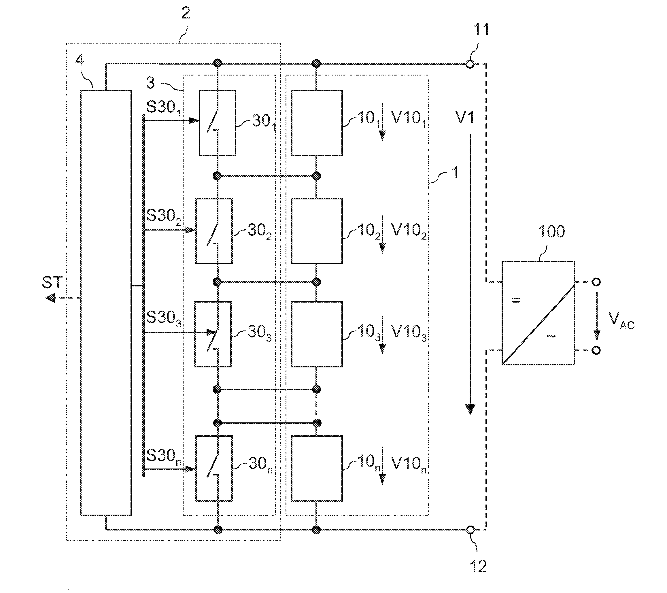
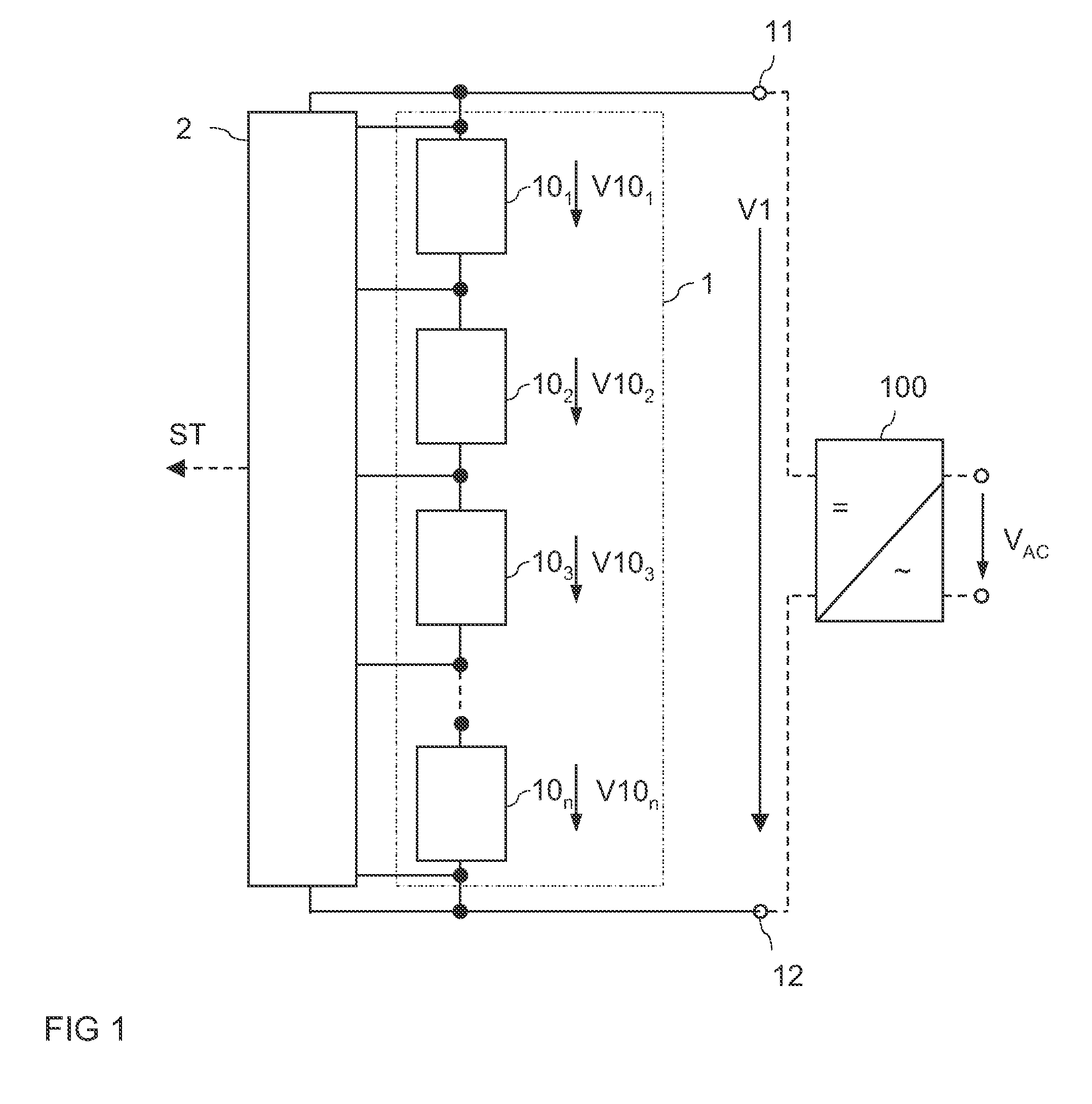
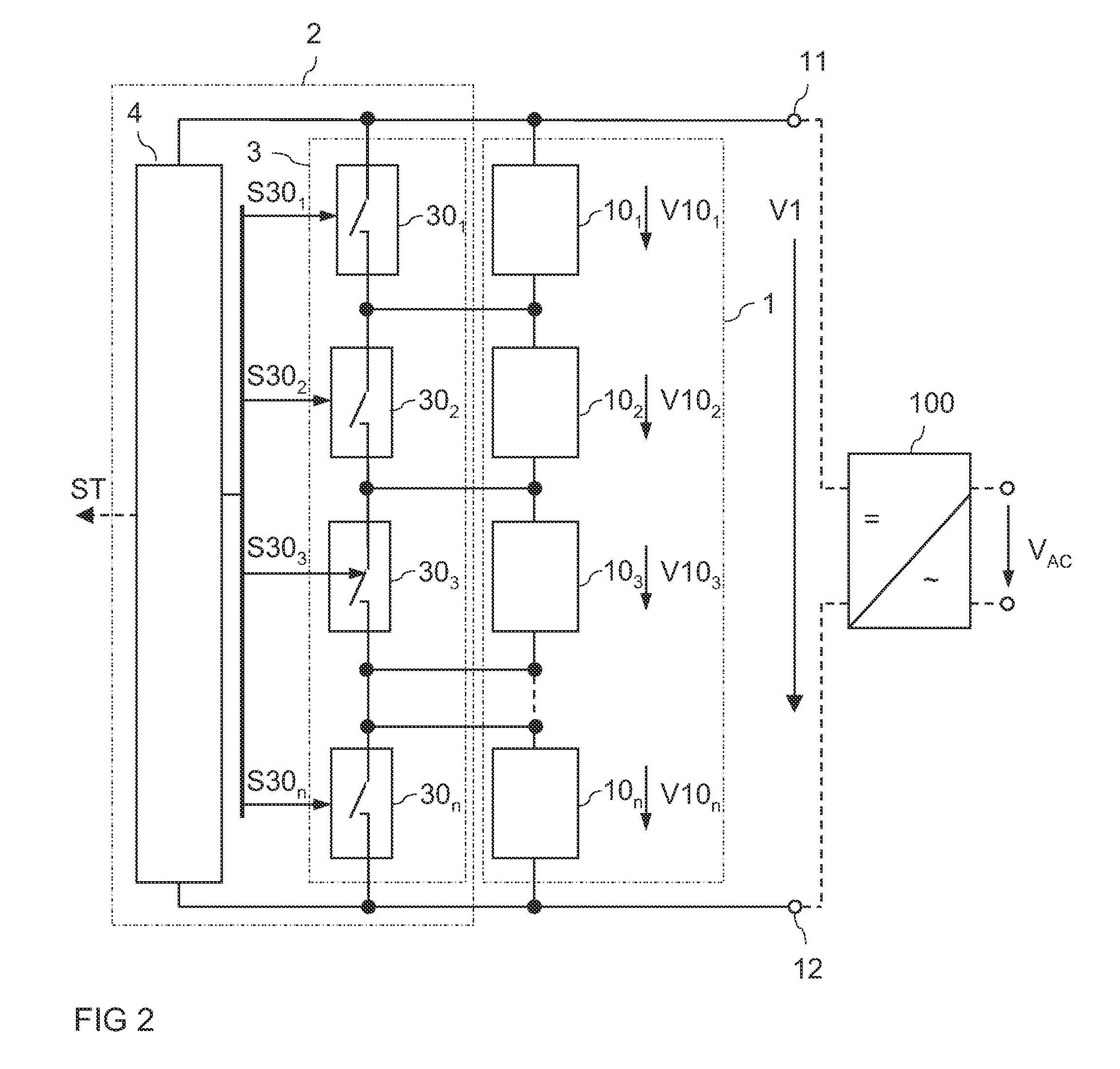
An embodiment method of diagnosing a power source arrangement includes a plurality of n power sources connected in series between output terminals, wherein n≧2. At least two different groups of power sources are selected from the power source arrangement. A voltage of each of the at least two different groups is measured between the output terminals. During the measurement of the voltage of one group, the power sources of the power source arrangement that do not belong to the one group are bypassed. The at least two measured voltages obtained through measuring the voltage of each of the at least two different groups or at least two voltages that are dependent on these at least two measured voltages are compared.

Description

TECHNICAL FIELD[0001]Embodiments of the present invention relate to a power source arrangement, in particular a power source arrangement including several power sources, such as photovoltaic (PV) modules, connected in series.BACKGROUND[0002]With an increasing interest in sustainable energy production there is a focus on using photovoltaic modules for producing electric power. Photovoltaic (PV) modules include a plurality of photovoltaic (PV) cells, that are also known as solar cells. Usually several solar modules are connected in series to form a string of modules. A DC output voltage provided by the string may then be converted into an AC voltage, such as, for example, a voltage suitable to be supplied to a power grid or to drive a motor.[0003]In an ideal case each of the modules connected in series provides the same output voltage. In real photovoltaic arrangements there may be modules that provide a lower voltage than other modules. This may be due to wear, corrosion of contacts ...

Claims


Application Information

Patent Timeline
IPC IPC(8): G01R19/00
CPCG01R31/025G01R31/42G01R31/40G01R19/0038G01R19/00H02S50/10G01R31/31721H02S50/00Y02E10/50
Inventor DEBOY, GERALD
Owner INFINEON TECH AUSTRIA AG
Learn More