Vibration isolation unit

a technology of vibration isolation and unit, which is applied in the direction of shock absorbers, machine supports, jet propulsion mountings, etc., can solve the problems of increasing product cost, increasing man-hour and material costs, and inefficient use of rubber materials, so as to improve the efficiency of manufacturing process and compact assembly equipment. , the effect of improving the efficiency of the manufacturing process

Inactive Publication Date: 2013-05-09
TOYO TIRE & RUBBER CO LTD
View PDF38 Cites 19 Cited by
  • Summary
  • Abstract
  • Description
  • Claims
  • Application Information

AI Technical Summary

Benefits of technology

[0026]According to the vibration isolation unit of the sixth aspect of the present invention, assembling of the liquid-sealed vibration isolation device (filling the liquid-sealed chamber with liquid) can be performed after the outer tube member is pressed-in to the pressed-in part of the engine side bracket because the liquid-sealed vibration isolation device includes the decompressing-cum-pouring hole that allows the liquid-sealed chamber to communicate with the outside and a sealer that seals the decompressing-cum-pouring hole, and, as a result, assembling equipment can be made compact and the efficiency of the manufacturing process can be improved.
[0027]That is, in the vibration isolation unit of the sixth aspect of the present invention, in order to press-in the outer tube member of the liquid-sealed vibration isolation device to the pressed-in part of the engine side bracket after assembling the liquid-sealed vibration isolation device in the liquid, it is required to fold the stopper rubber member so as not to be obstructive in pressing-in...

Problems solved by technology

Further, rubber material is used inefficiently because a part of the first stopper rubber 86 covering the upper surface of the vibration isolation device body 18 overlaps with a part of the diaphragm 30 in an axi...

Method used


Image

  • Vibration isolation unit
  • Vibration isolation unit
  • Vibration isolation unit

Examples


Embodiment Construction

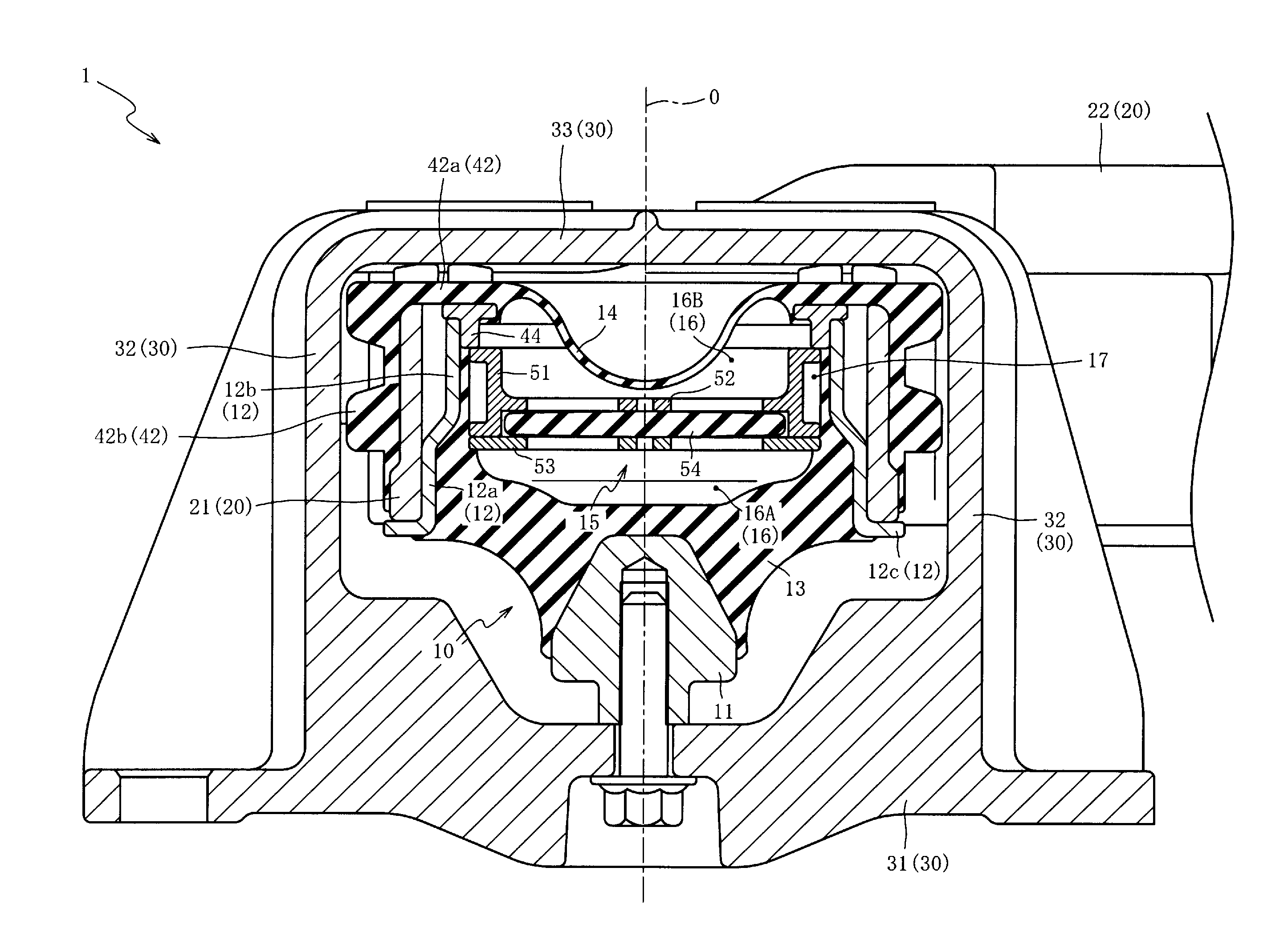
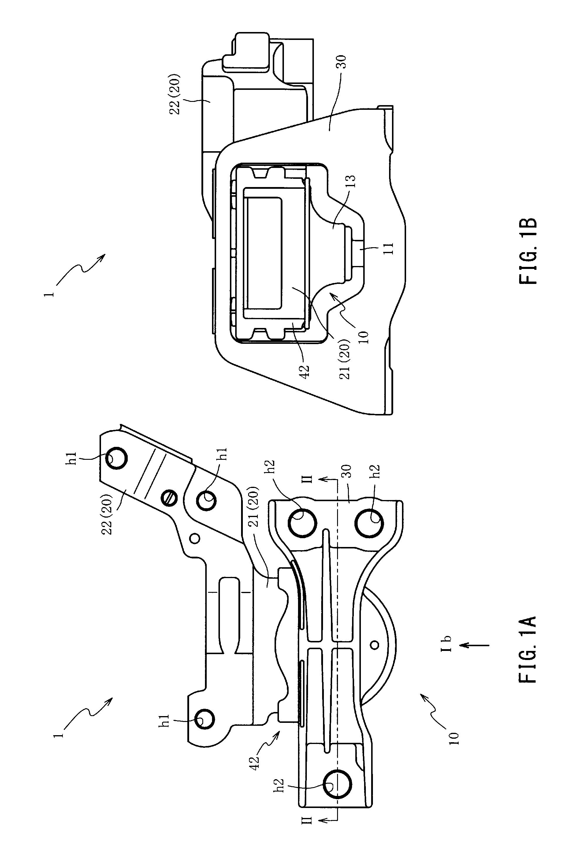
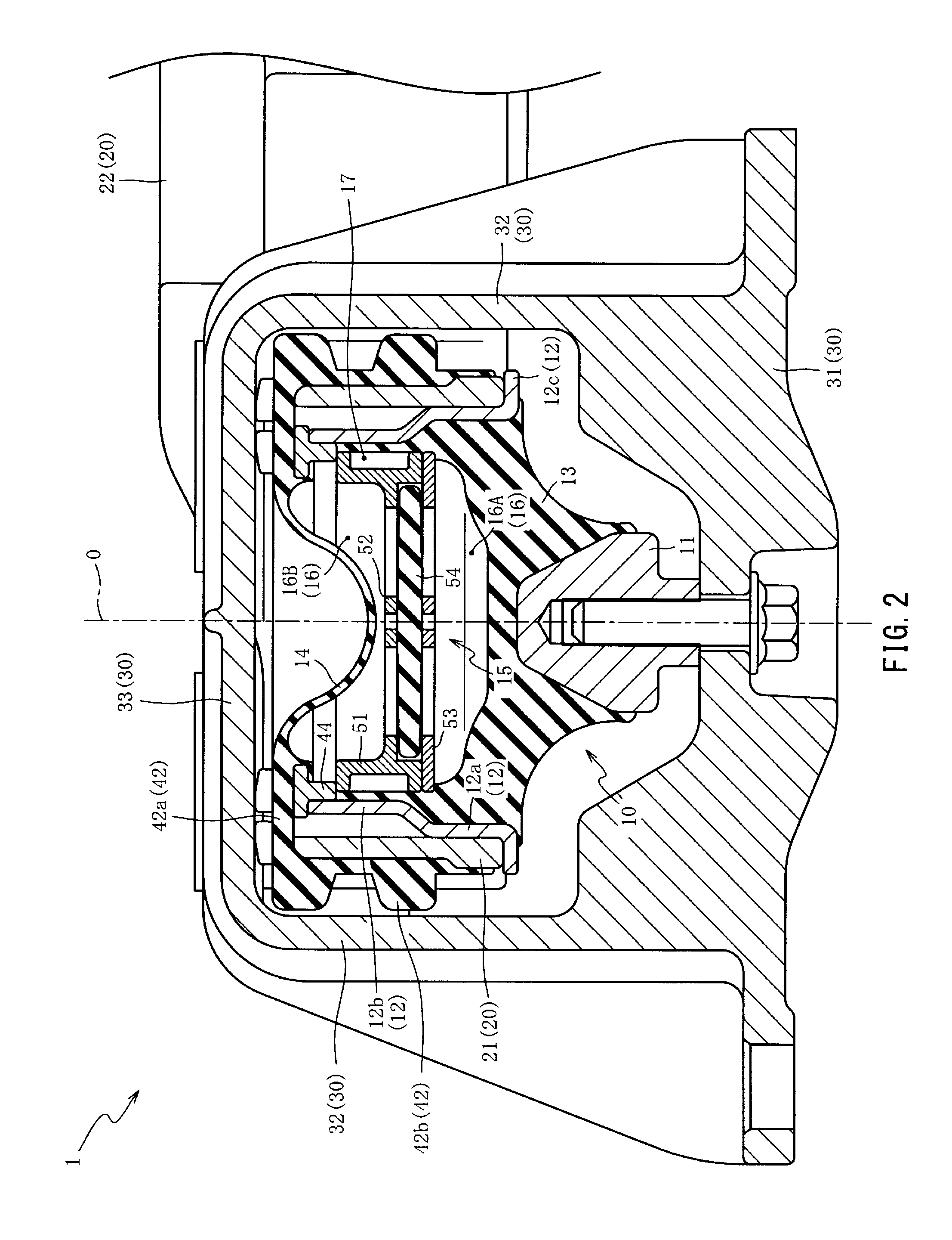
[0040]Hereinafter, the preferred examples of the present invention will be described referring to the attached drawings. First, the overall constitution of a vibration isolation unit 1 will be described referring to FIG. 1A, FIG. 1B and FIG. 2.

[0041]FIG. 1A is a top view of the vibration isolation unit 1 of a first embodiment of the present invention, and FIG. 1B is a front view of the vibration isolation unit 1 when viewed from the direction of the arrow Ib of FIG. 1A. FIG. 2 is a cross-sectional view of the vibration isolation unit 1 taken from the line II-II of FIG. 1A. Further, FIG. 2 corresponds to a cross section including the axis O. Furthermore, in FIG. 2, a bolt is illustrated not by the cross-sectional view.

[0042]As shown in FIG. 1A, FIG. 1B and FIG. 2, the vibration isolation unit 1 is a device for suppressing vibration of an engine (not shown) of an automobile from being transmitted to a vehicle body (not shown) while supporting and fixing the engine, and includes a vibr...


PUM


Abstract

To provide a vibration isolation unit capable of reducing the number of parts, man-hour and material cost, and suppressing the product cost. One side of a stopper rubber member continues to the outer edge of a diaphragm. Accordingly, because they can be vulcanizingly molded simultaneously, the number of parts can be reduced. Also, because the diaphragm is attached to an outer tube member, the stopper rubber member also can be fixed simultaneously, and therefore the man-hour can be reduced. Further, because one side of the stopper rubber member continues to the outer edge of the diaphragm, overlapping of them in an axial view can be avoided, and a rubber material can be used efficiently. Thus, the number of parts, man-hour and material cost can be reduced and the product cost of the overall vibration isolation unit can be suppressed.

Description

BACKGROUND OF THE INVENTION[0001]1. Field of the Invention[0002]The present invention relates to a vibration isolation unit, and relates specifically to a vibration isolation unit that can reduce the number of parts, man-hour and material cost, and can thereby suppress the product cost.[0003]2. Description of the Related Art[0004]As a vibration isolation unit preventing vibration of an engine for an automobile from being transmitted to a vehicle body while supporting and fixing the engine, one provided with a liquid-sealed vibration isolation device is known. In the vibration isolation unit, the liquid-sealed vibration isolation device is interposed between the engine and the vehicle body through an engine side bracket and a vehicle body side bracket.[0005]For example, in Japanese Unexamined Patent Application Publication No. 2009-14080 (refer to FIG. 1 to FIG. 3, FIG. 14 to FIG. 16, paragraphs 0029, 0036 to 0038, and the like), an inverted type vibration isolation unit is disclosed...

Claims


Application Information

Patent Timeline
IPC IPC(8): F16M13/02F16F13/10
CPCF16F13/101B60K5/1266
Inventor KATO, HIRONORISAKATA, TOSHIFUMIOKAMURA, TAKESHIONIWA, TATSUYA
Owner TOYO TIRE & RUBBER CO LTD
Why Eureka
Try Eureka