Image processing device, image processing method, and image processing program

Inactive Publication Date: 2013-05-09
FUJIFILM CORP
View PDF3 Cites 8 Cited by
  • Summary
  • Abstract
  • Description
  • Claims
  • Application Information

AI Technical Summary

Benefits of technology

[0022]According to the present invention, parallax amounts among a plurality of images are calculated for each subject within images. The subjects having an absolute parallax value which exceeds a first predetermined amount are identified as subjects targeted for display position adjustment, using a cross point provisionally set for the plurality of images as a reference, and parallax is gradually adjusted such that the absolute parallax value of the subjects targeted for display position adjustment does not exceed a second predetermined amount after adjustment so that the stereoscopic effect of stereoscopic images can be appropriately adjusted and the cross-point position is gradually changed, which can prevents users from feeling discomfort at the time of adjustment. Further, in such case, subjects having an absolute parallax value which exceeds a third predetermined amount are identified as subjects to be blurred, in each of an image representing a provisional cross-point position, an image being subjected to parallax adjustment, an image after parallax adjustment; and the subjects to be blurred are blurred in images so as to avoid directing a user' s attention toward the subject which are projected excessively forward. Thus, this can reduce the burden on us

Problems solved by technology

Thus, there is a problem that this rapid change of the parallax amount causes a user to feel d

Method used


Image

  • Image processing device, image processing method, and image processing program
  • Image processing device, image processing method, and image processing program
  • Image processing device, image processing method, and image processing program

Examples


first embodiment

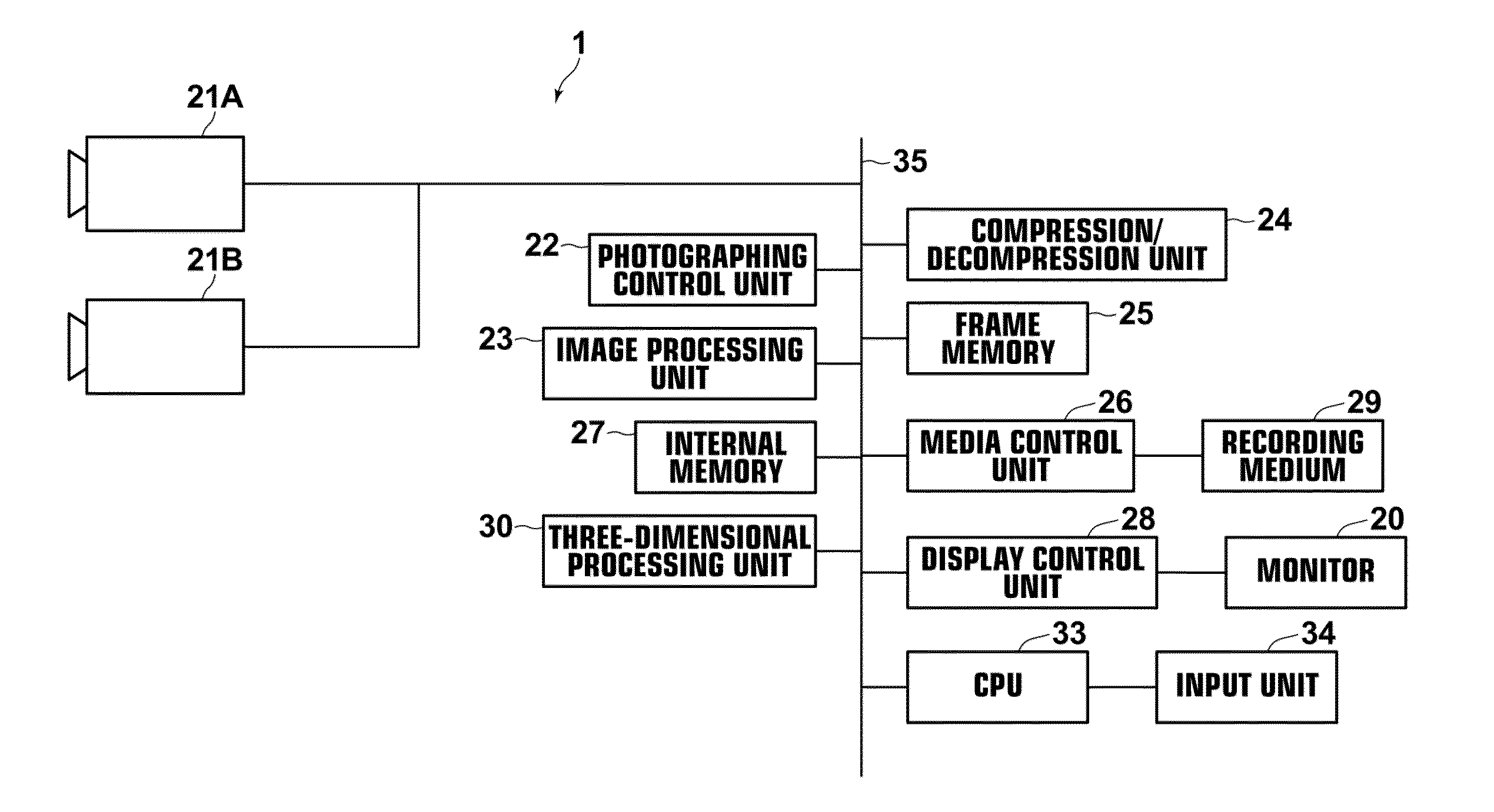
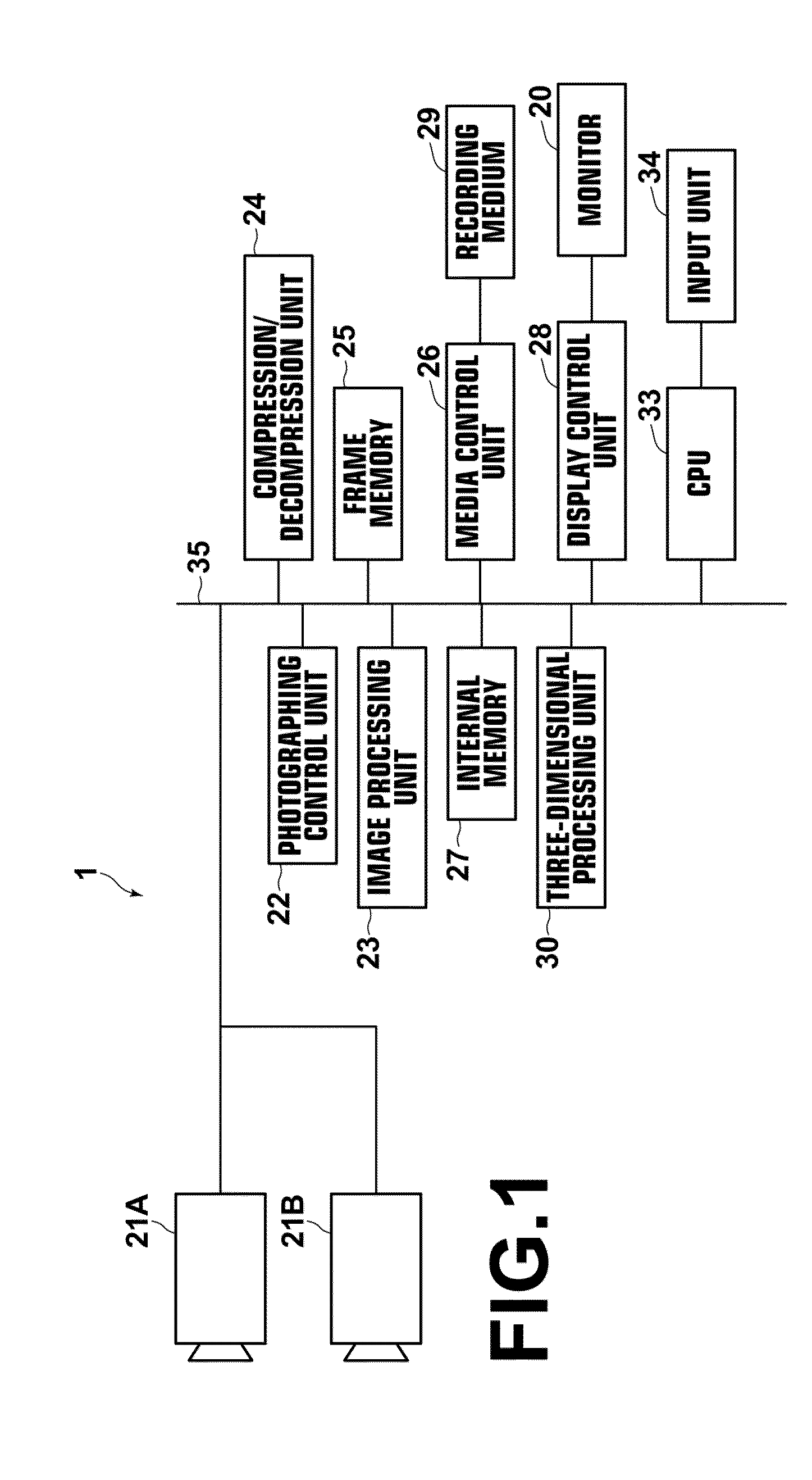
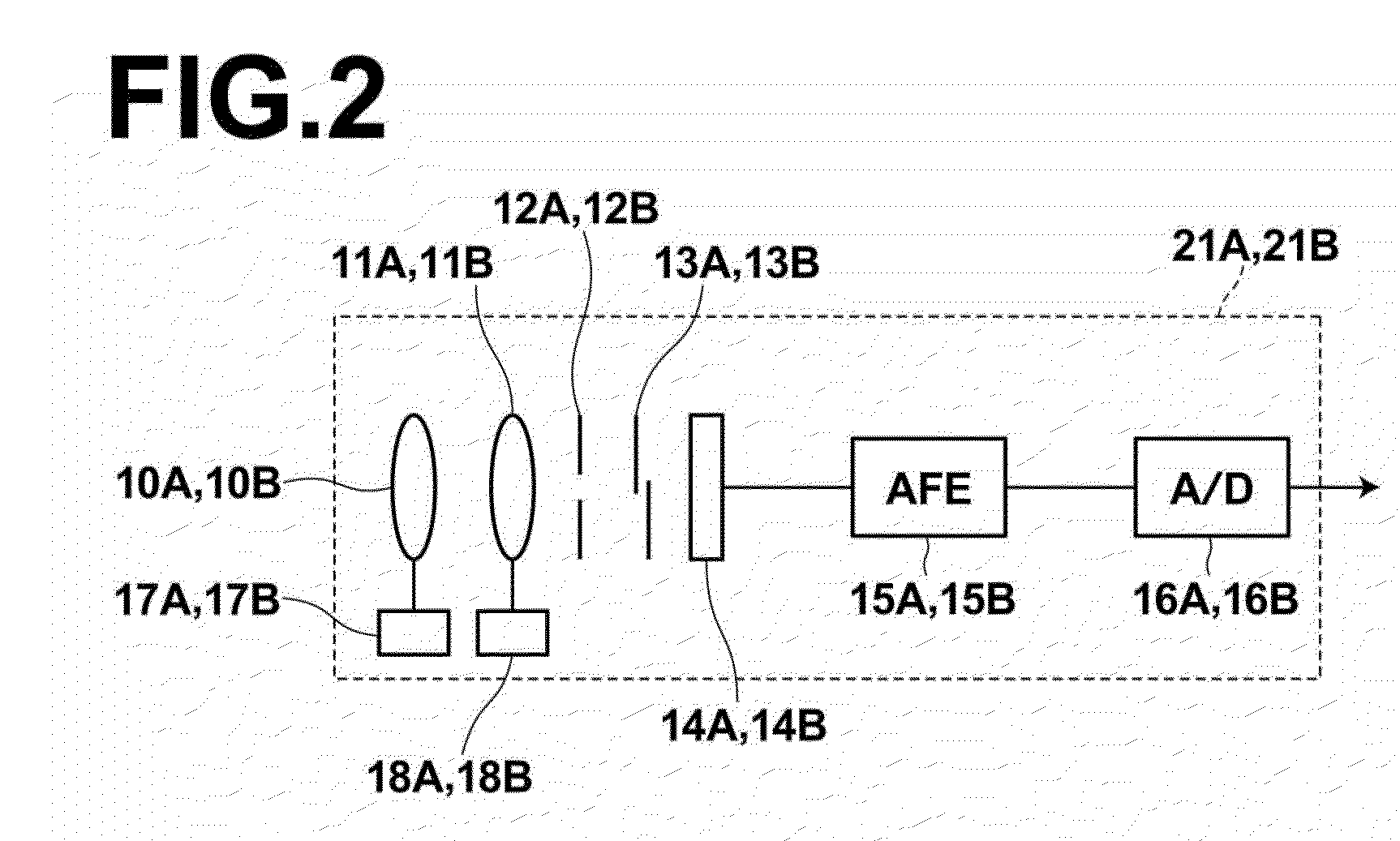
[0047]Hereinafter, embodiments of the present invention will be described with reference to the drawings. FIG. 1 is a schematic block diagram that illustrates the internal configuration of a polynocular camera, to which an image processing apparatus according to the invention is applied. FIG. 2 is a schematic block diagram that illustrates the configuration of an imaging unit of the polynocular camera. FIG. 3 is a schematic block diagram that illustrates the configuration of a three dimensional processing unit of the polynocular camera.

[0048]As shown in FIG. 1, the polynocular camera 1 according to the first embodiment includes two imaging units 21A and 21B, a photographing control unit 22, an image processing unit 23, a compression / decompression unit 24, a frame memory 25, a media control unit 26, an internal memory 27, a display control unit 28, a three-dimensional processing unit 30 and a CPU 33. The imaging units 21A and 21B are placed to be able to photograph a subject with a p...

second embodiment

[0112]A polynocular camera is mainly characterized in that only faces are specified as subjects targeted for display position adjustment among the subjects located forward away from the provisional cross point position, and the cross point position is gradually adjusted from the provisional cross point to the cross point position after adjustment such that the subjects targeted for display position adjustment do not move forward away from the cross point position after adjustment.

[0113]The polynocular camera according to the second embodiment differs from the polynocular camera according to the first embodiment in the configuration of the three-dimensional processing unit and in that the polynocular camera according to the second embodiment includes a face detecting means for detecting faces from the images GR, GL.

[0114]As shown in FIG. 10, the three-dimensional processing unit 30a of the present embodiment includes a blur circuit 41, a feature point detection circuit 42, a vector ...

third embodiment

[0133]The polynocular camera is mainly characterized in that only the subjects, which are within a predetermined range of the centers of images, are specified as subjects targeted for display position adjustment, among the subjects which are located forward away from the provisional cross point position and the cross point position is gradually adjusted from the provisional cross point to the cross point position after adjustment such that the subjects targeted for display position adjustment do not move forward away from the cross point position after adjustment.

[0134]The polynocular camera according to the third embodiment differs from the polynocular camera according to the first embodiment only in the configuration of the three-dimensional processing unit.

[0135]As shown in FIG. 12, the three-dimensional processing unit 30b of the present embodiment includes a blur circuit 41, a feature point detection circuit 42, a vector detection circuit 43, a projecting region calculation ci...


PUM


Abstract

A parallax amount between the plurality of images for each subject on the images is calculated, a subject having an absolute parallax value which exceeds a first predetermined amount as a subject targeted for display position adjustment, using a cross point provisionally set for the plurality of images as a reference is identified, and parallax is gradually adjusted such that the absolute parallax value of the subject targeted for display position adjustment does not exceed a second predetermined amount after adjustment. In this case, a subject having an absolute parallax value which exceeds a third predetermined amount is identified as a subject to be blurred, in each of an image having the provisional cross-point position, an image undergoing parallax adjustment, and an image after the parallax adjustment, and a blur process is performed on the subject to be blurred within the images.

Description

TECHNICAL FIELD [0001]The present invention relates to an image processing device and an image processing method for performing three-dimensional processing on a plurality of images with different viewpoints to enable stereoscopic viewing of the images, and for generating stereoscopic images which are stereoscopically displayed on a display means for stereoscopically display, as well as a program for causing a computer to carry out the three-dimensional processing method.BACKGROUND ART[0002]Enabling stereoscopic viewing utilizing parallax by combining a plurality of images obtained by imaging the same subject from different positions such that stereoscopic images are generated, thereby stereoscopically displaying the generated stereoscopic image, is known. As a specific method for the stereoscopic display, a naked-eye parallel viewing method that stereoscopically displays images by arranging a plurality of images side by side is known. Further, the three-dimensional display may be a...

Claims


Application Information

Patent Timeline
IPC IPC(8): G06T15/00H04N13/128
CPCH04N13/0022G06T15/00H04N2013/0081H04N13/122H04N13/128
Inventor UCHIDA, AKIHIRO
Owner FUJIFILM CORP
Why Eureka
Try Eureka