Internal gear pump

a gear pump and gear box technology, applied in the direction of liquid fuel engines, machines/engines, rotary piston liquid engines, etc., can solve the problems of unimproved volume efficiency and unimproved volume efficiency, and achieve the effect of improving volume efficiency, smooth formation, and suppressing leakag

Active Publication Date: 2013-05-09
YAMADA SEISAKUSHO KK
View PDF2 Cites 3 Cited by
  • Summary
  • Abstract
  • Description
  • Claims
  • Application Information

AI Technical Summary

Benefits of technology

[0019]A radial clearance between the outer rotor and the rotor housing chamber is uniform along the outer circumference (360°). The rotation of the outer rotor is smoothly performed. A meshing range of the inner rotor and the outer rotor is further in a negative range in the rotating direction than the deepest meshing section. Therefore, a tip clearance between the inner rotor and the outer rotor in the maximum cell volume section on the conveyance side decreases. As a result, it is possible to suppress a leak from the maximum cell volume section and improve volume efficiency.
[0020]In the third aspect, the tooth profile of the inner rotor is formed by a curve obtained by combining a plurality of ellipses and circles or high-order curves. Therefore, a joining section is smoothly formed and durability of the rotors is improved. It is possible to reduce sound caused when the rotors mesh with each other. Therefore, silence is also improved.

Problems solved by technology

Therefore, volume efficiency is not improved.

Method used


Image

  • Internal gear pump
  • Internal gear pump
  • Internal gear pump

Examples


Embodiment Construction

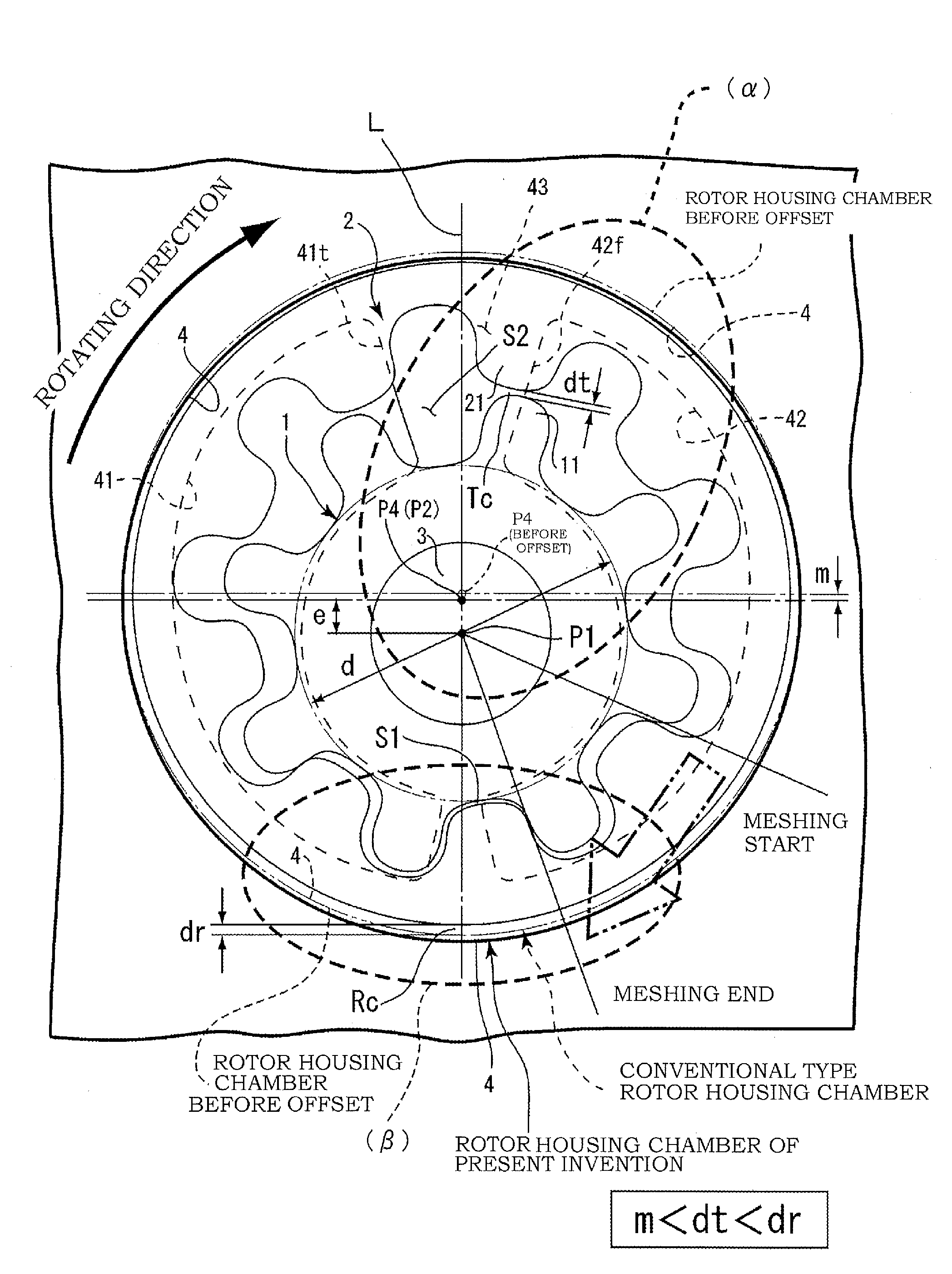
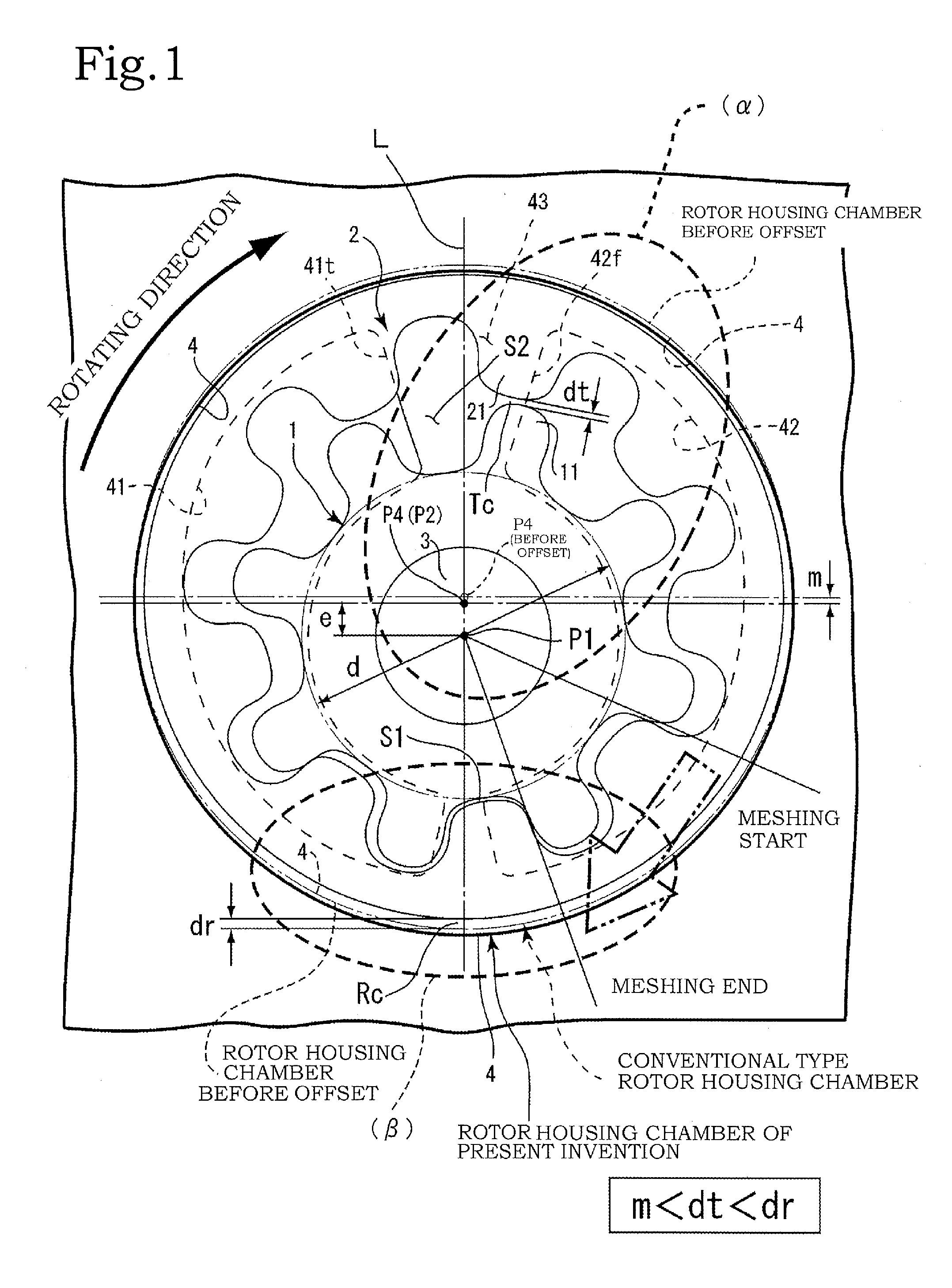
[0025]An embodiment of the present invention is explained below on the basis of the drawings. In the present invention, a pump rotor configures a rotor of an internal gear pump. Specifically, the pump rotor includes an inner rotor 1 and an outer rotor 2 (see FIG. 1). The inner rotor 1 is a gear of an external gear type and the outer rotor 2 is a gear of an internal gear type. In FIG. 1, an arrow of an alternate long and two short dashes line drawn in a range from the start of meshing to the end of meshing indicates force applied from the inner rotor 1 to the outer rotor 2.

[0026]The pump rotor refers to a so-called high-volume tooth profile, which realizes an increase in a theoretical discharge amount, rather than the trochoid tooth profile. As the high-volume tooth profile, a tooth profile 11 of the inner rotor 1 is formed by, for example, a curve obtained by combining a plurality of ellipses and circles or high-order curves.

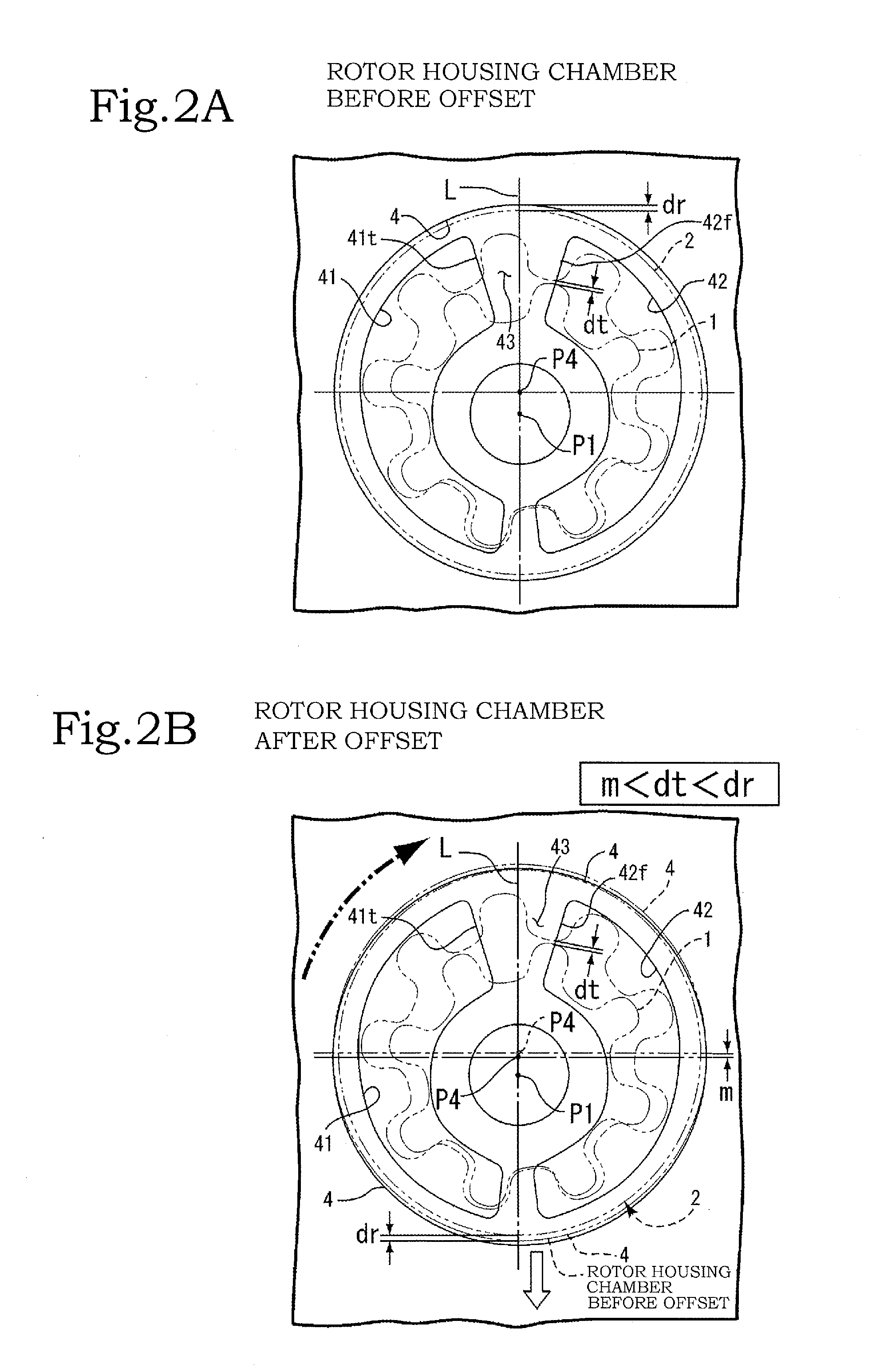
[0027]In the present invention, in the pump rotor, the rot...


PUM


Abstract

An internal gear pump in which an inner rotor and an outer rotor are arranged in a rotor housing chamber. A deepest meshing section is located in the vicinity on a line connecting a center of the inner rotor and a center of the outer rotor. A center of the rotor housing chamber is offset, from a position in which the center and the center of the outer rotor coincide with each other, to the deepest meshing section side by an amount smaller than a tip clearance, which is a gap between the tooth tip of the inner rotor and the tooth tip of the outer rotor in the vicinity of a seal land between a terminal end side of an intake port and a start end side of a discharge port.

Description

BACKGROUND OF THE INVENTION[0001]1. Field of the Invention[0002]The present invention relates to an internal gear pump that can improve volume efficiency.[0003]2. Description of the Related Art[0004]Conventionally, there is an internal gear pump including an inner rotor and an outer rotor. Concerning tooth profiles of the inner rotor and the outer rotor, various researches and developments have been conducted and inventions for improving pump efficiency have been devised. As such inventions, there are Japanese Patent Application Laid-open No. S55-148992 and WO2008 / 111270.[0005]In Japanese Patent Application Laid-open No. S55-148992, teeth of an inner rotor start to push (or start to mesh with) teeth of an outer rotor in a deepest meshing section. Consequently, force is applied to the outer rotor from the deepest meshing section to a front side in a rotating direction of the rotors. In other words, force in a direction substantially lateral to a conveying side, which is a maximum cel...

Claims


Application Information

Patent Timeline
Patent Type & Authority Applications(United States)
IPC IPC(8): F01C1/00
CPCF01C1/00F04C2/102F04C2/084
Inventor FUJIKI, KENICHIIZUTSU, MASATO
Owner YAMADA SEISAKUSHO KK
Why Eureka
Try Eureka