Dust collecting attachment for electric power tool and electric power tool

a technology for electric power tools and attachments, which is applied in the direction of vehicle maintenance, manufacturing tools, vehicle cleaning, etc., can solve the problems of affecting operability, affecting workability, and difficulty for the operator to hold the handle portion, and achieve the effect of stable connection of the pip

Active Publication Date: 2013-05-09
MAKITA CORP
View PDF10 Cites 16 Cited by
  • Summary
  • Abstract
  • Description
  • Claims
  • Application Information

AI Technical Summary

Benefits of technology

[0018]According to the seventh aspect of the invention, in addition to the effects of the fifth aspect, the protrusion and the through hol

Problems solved by technology

In such a conventional dust collecting attachment, however, in the case where the tool body is used as a handle portion for the operator, the operator needs to hold the handle portion together with the hose on the lower side.
Thus,

Method used


Image

  • Dust collecting attachment for electric power tool and electric power tool
  • Dust collecting attachment for electric power tool and electric power tool
  • Dust collecting attachment for electric power tool and electric power tool

Examples


first embodiment

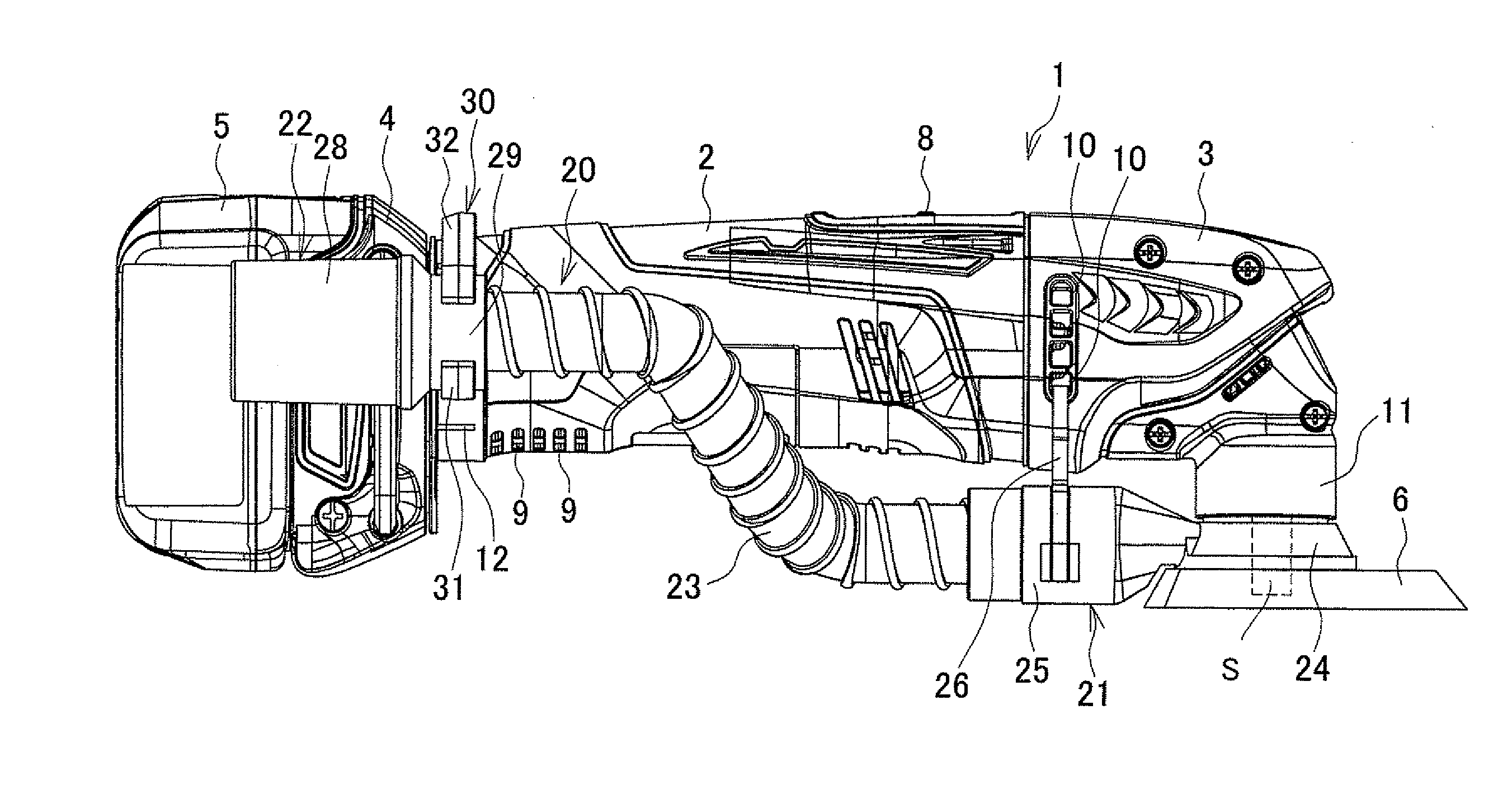
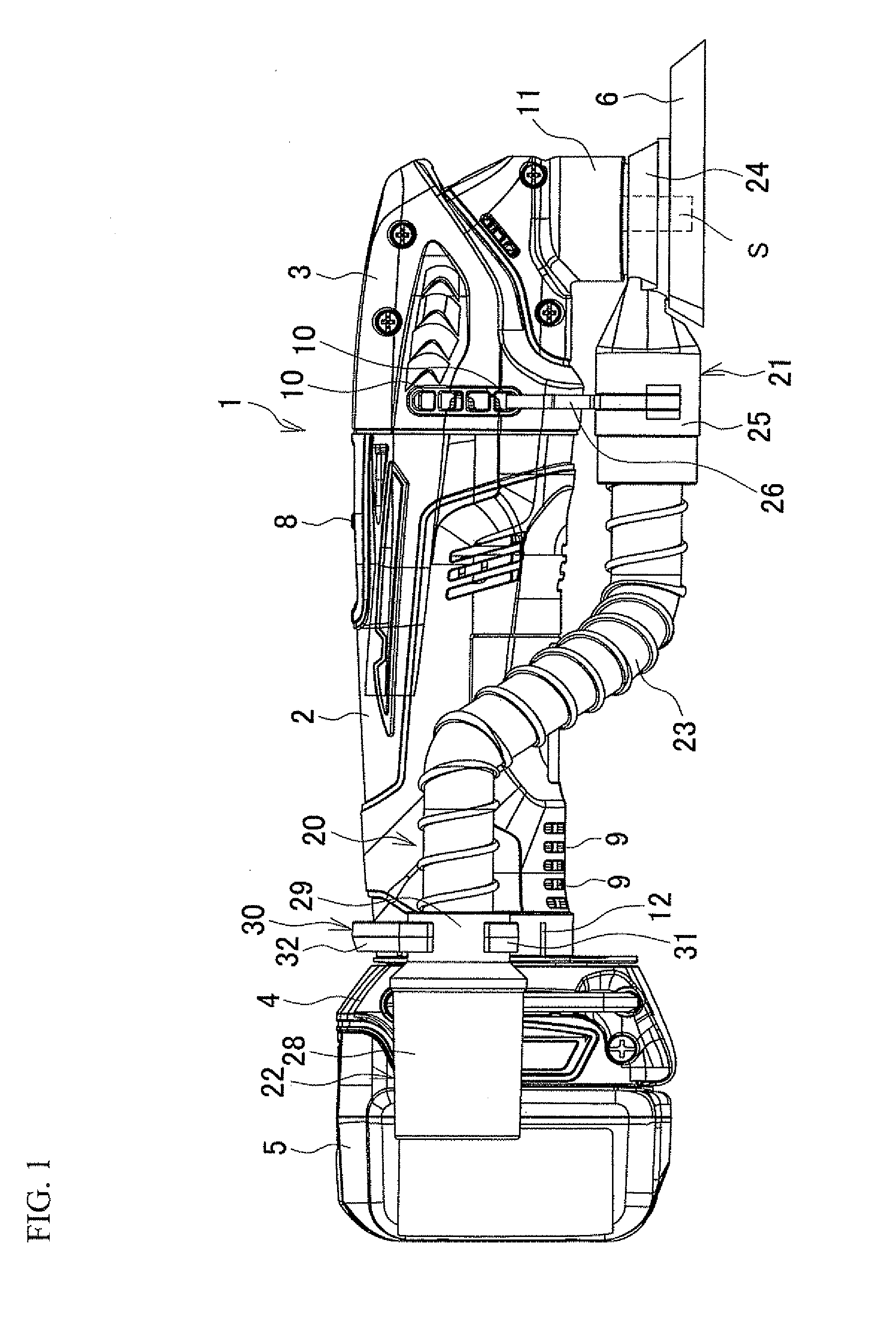
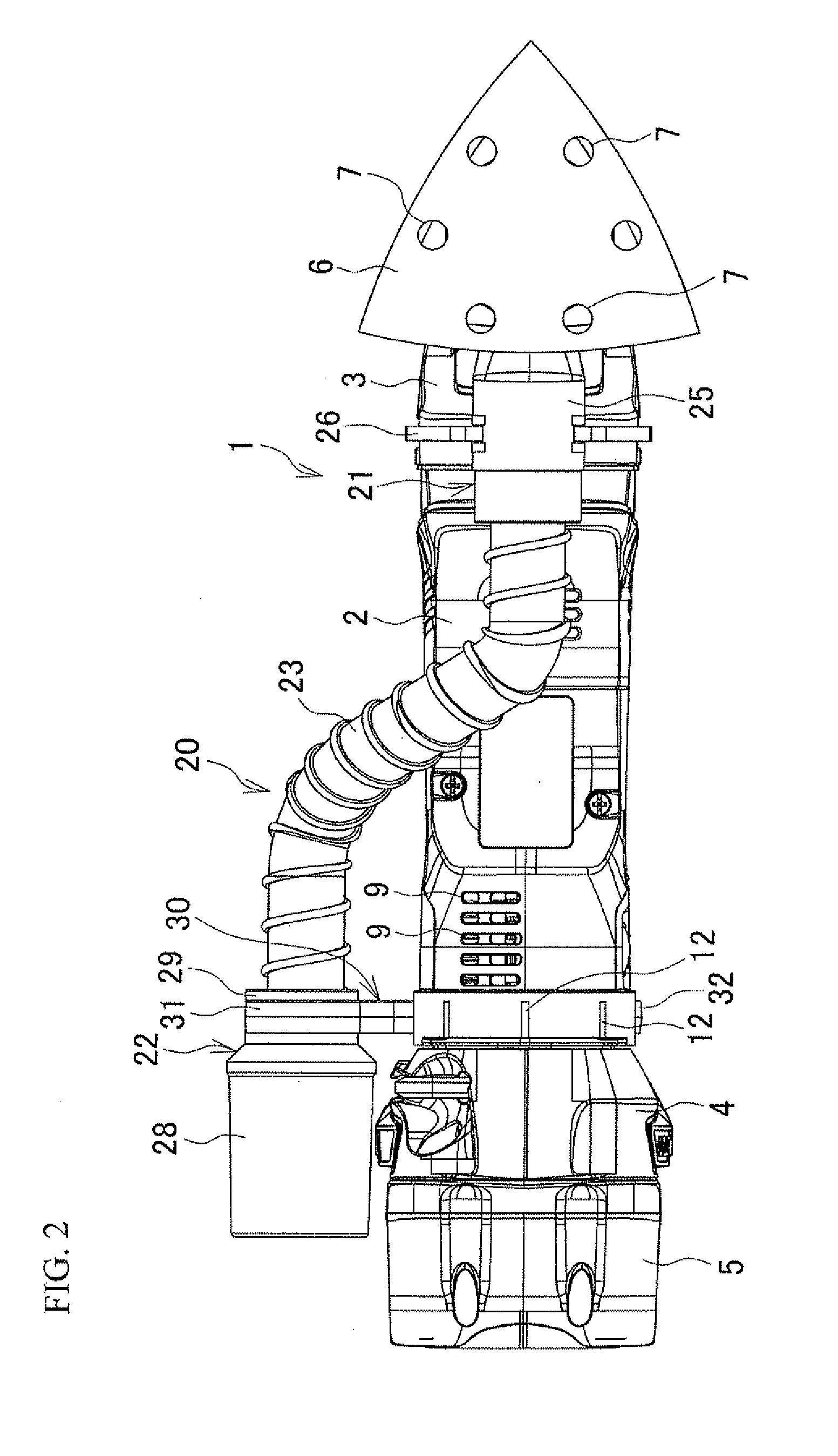
[0031]FIG. 1 is a side view of a sander as an example of an electric power tool, and FIG. 2 is a bottom view thereof. In a sander 1, a front housing 3 is connected to the front (the right side in FIG. 1) of a cylindrical motor housing 2, and a battery pack 5 as a power source is mounted on a mounting portion 4 formed at the rear end of the motor housing 2. The motor housing 2 accommodates a motor, not shown, and an output shaft S is in a lower portion of the front housing 3 so as to project downward from the front housing 3, as shown in FIG. 1. A swing mechanism, not shown, which converts rotation of a motor shaft to lateral swing motion of the output shaft S is contained in the front housing 3. A base 6, which has a triangular shape as viewed in plan, is mounted on the lower end of the output shaft S perpendicularly to the direction in which the output shaft S extends, and a plurality of dust collecting holes 7, 7 are formed in the base 6 so as to extend therethrough. A switch 8 is...

second embodiment

[0047]Another embodiment will be described below. It should be noted that the configuration of the sander 1 is the same as that of the first embodiment. Therefore, overlapping description will be omitted, and the dust collecting attachment will be mainly described.

[0048]In FIGS. 6 and 7, a dust collecting attachment 20A mounted on the sander 1 has a suction portion 21 in a front part of the dust, and a discharge portion 22 in its rear part, as shown in FIG. 8. Further, the suction portion 21 and the discharge portion 22 are connected by a flat pipe 34.

[0049]The suction portion 21 comprises a short cylindrical holder ring 35 placed above a base 6 and fitted on a cylinder portion 11, and a flat tube shaped front joint 36 connected to the lateral surface of the holder ring 35 in a radial direction and in an obliquely upward direction. As in the first embodiment, the discharge portion 22 includes a cylindrical rear joint 28 to which the rear end of the pipe 34 is connected by insertion,...


PUM


Abstract

A dust collecting attachment that is mounted on a sander includes a suction portion mounted on a portion of a front housing where an output shaft projects, a flexible hose having a front end of the flexible hose connected to the suction portion, a discharge portion connected to a rear end of the flexible hose and a changeable member placed on both a motor housing and the discharge portion. The changeable member allows the discharge portion to be mounted at any position around an axis of the motor housing.

Description

BACKGROUND OF THE INVENTION[0001]This application claims the benefit of Japanese Patent Application Number 2011-244772 filed on Nov. 8, 2011, the entirety of which is incorporated by reference.TECHNICAL FIELD[0002]The present invention relates to dust collecting attachments for electric power tools, which are mounted on electric power tools such as a sander so as to be used to collect power dust generated by processing a workpiece, and electric power tools using such dust collecting attachments.BACKGROUND ART[0003]Dust collecting attachments for electric power tools (hereinafter simply referred to as the “dust collecting attachments”), which can be connected to an external dust collecting device or a dust collecting bag, are mounted on electric power tools such as a sander and a grinder in order to collect, without scattering, power dust generated from a workpiece during processing. For example, a dust collecting attachment as described in, for example, Japanese Examined Patent Publ...

Claims


Application Information

Patent Timeline
IPC IPC(8): B24B55/10B08B13/00
CPCB23Q11/0046B24B55/10Y02P70/171
Inventor MIZUTANI, AKIRAMUTO, HIDEHARU
Owner MAKITA CORP
Why Eureka
Try Eureka