Windshield wiper

a technology of windshield wiper and wiper body, which is applied in the field of windshield wiper, can solve the problems of increasing the consumption of windshield wipers, increasing the cost, and complex structure, and achieve the effect of improving conformity

Inactive Publication Date: 2013-05-16
DONGGUAN HONGYI WIPER
View PDF7 Cites 40 Cited by
  • Summary
  • Abstract
  • Description
  • Claims
  • Application Information

AI Technical Summary

Benefits of technology

[0007]The object of the instant disclosure is to provide a wiper, and through the different curvatures of the flexible member, the wiper can be conformed to the windshield of the ca

Problems solved by technology

In order to ensure a safe ride, it has turned out to be a duty for car drivers to change their wipers regularly, and thereby, increasing the consumption of the wipers.
However, as such type of conventional wiper has disadvantages such as having a more complex structure, a higher cost, a more difficult manufacturing process, and a heavier weight, thus has gradually been replaced by soft wipers.
On the other hand, although conventional soft wipers have a simpler structure and a lighter weight, such wipers only employs its soft frame to exert for

Method used


Image

  • Windshield wiper
  • Windshield wiper
  • Windshield wiper

Examples


first embodiment

The First Embodiment

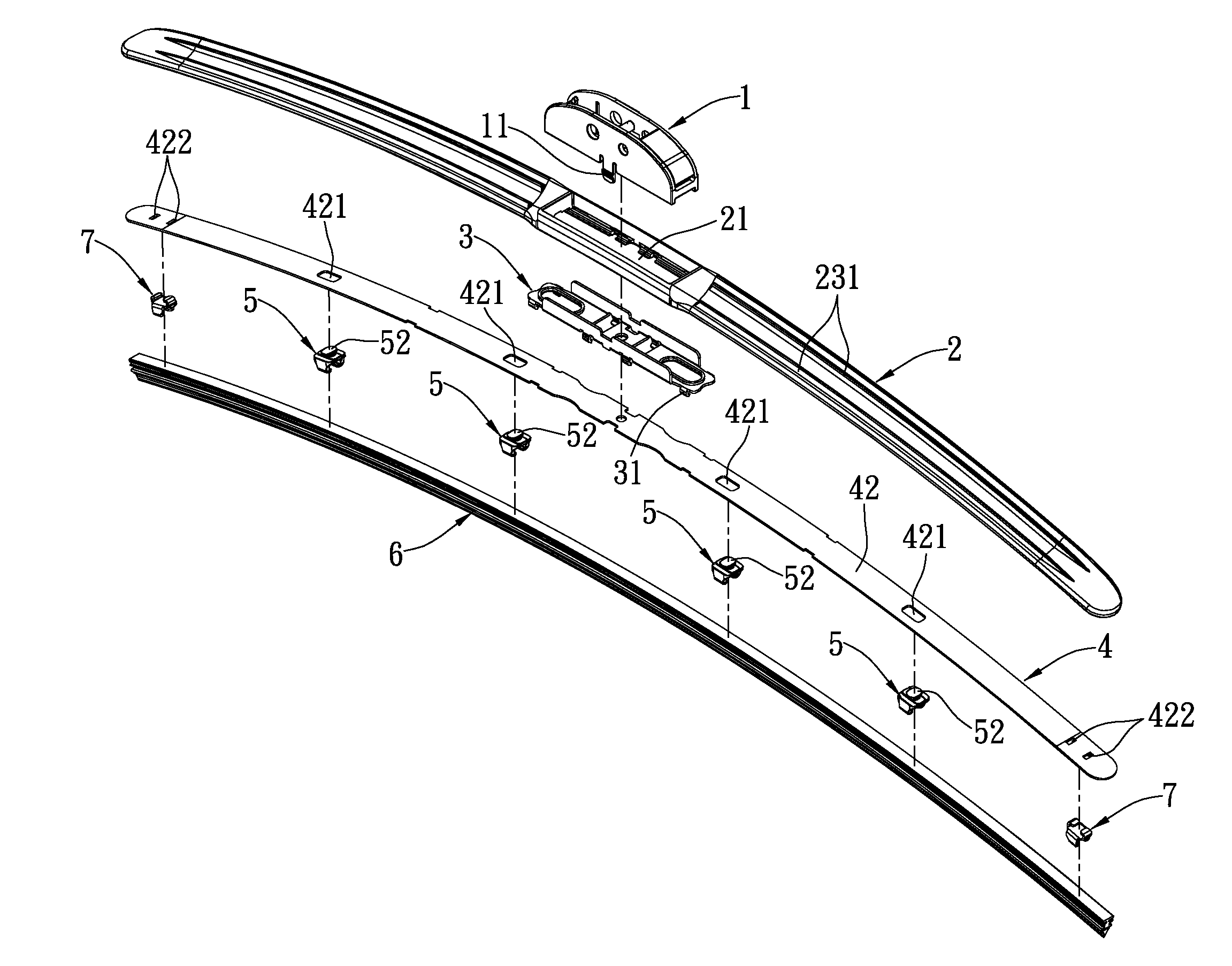
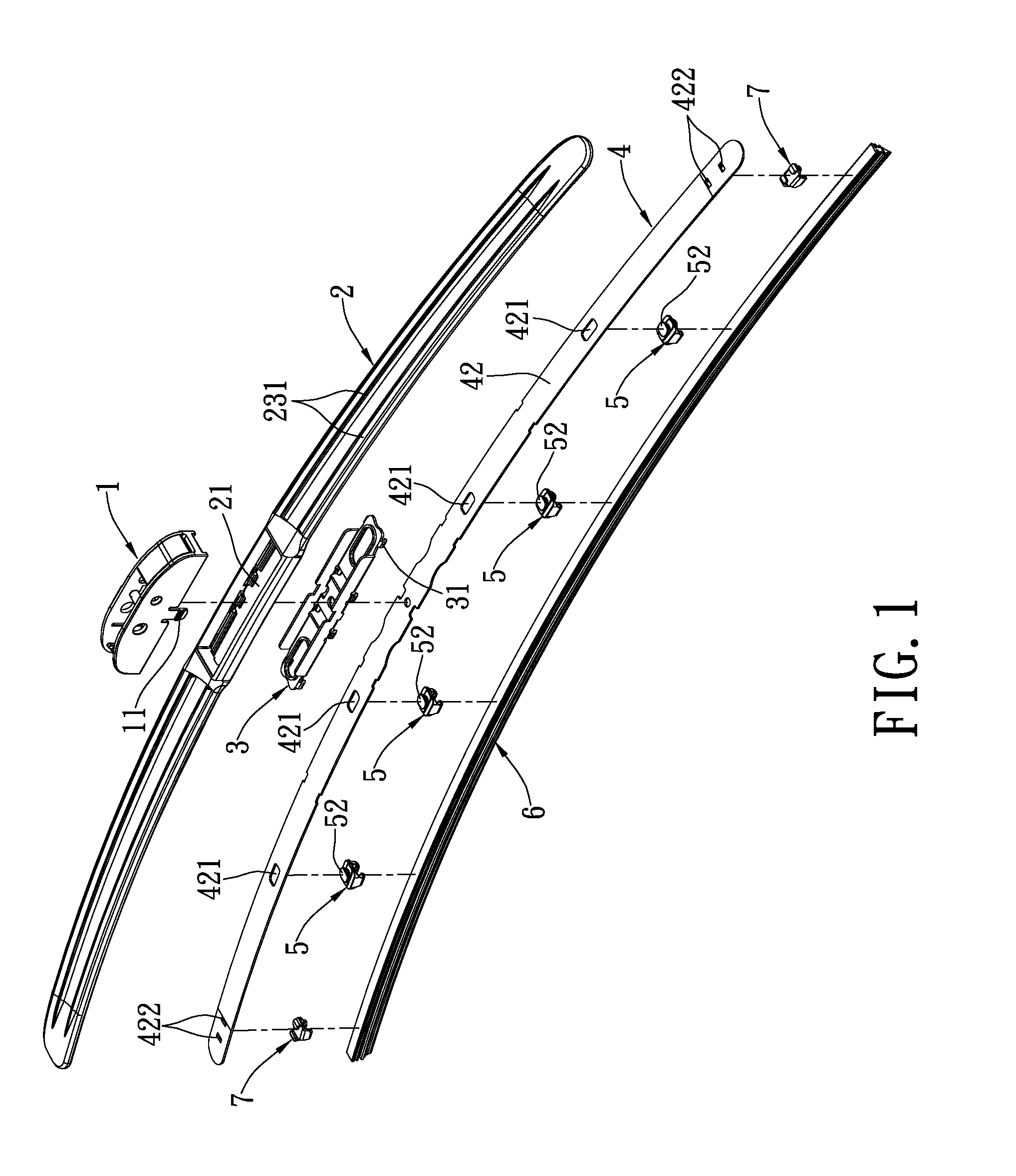
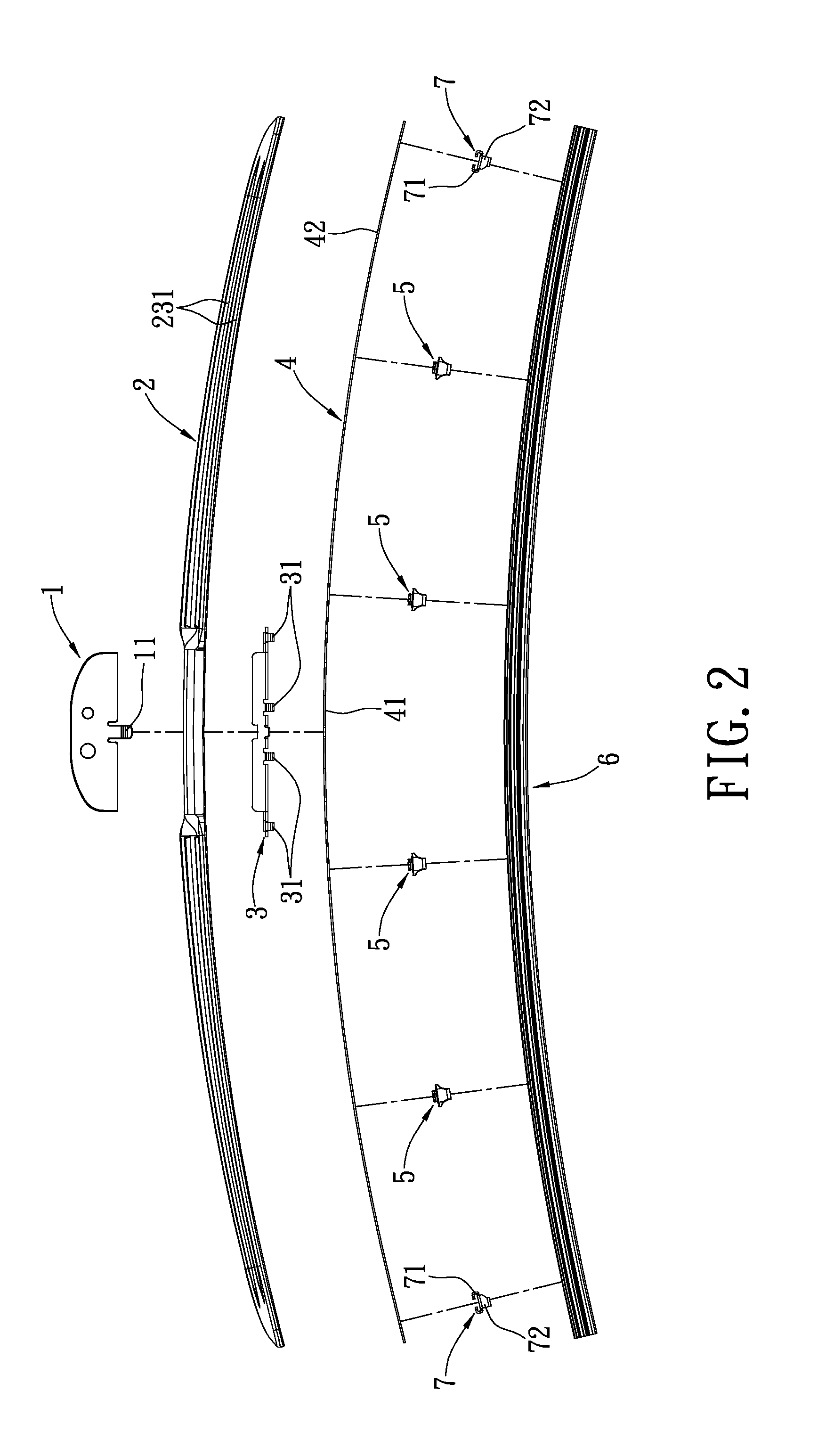
[0028]Please refer to FIGS. 1 and 2, the wiper of the instant disclosure includes a wiper connector 1, a reinforcing member 2, a rigid frame 3, a flexible member 4, a plurality of fastening member 5 and a wiper blade 6. The flexible member 4 has multiple curvatures formed thereon. To provide further explanations, the flexible member 4 is made up of a generally elongated central loading portion 41 and a second loading portion 42, where the central loading portion 41, having a zero curvature, is arranged in the center of the flexible member 4, and the second loading portion 42 extends substantially symmetrically from two ends of the central loading portion 41. Furthermore, the curvature of the second loading portion 42 is greater than that of the central loading portion 41.

[0029]The central loading portion 41 has a rigid frame 3 engaged thereon, where the rigid frame 3 has a plurality of folded portions 31 extending downwardly and inwardly for engagement to the cen...

second embodiment

The Second Embodiment

[0035]Please refer to FIGS. 7 and 8. The wiper of the instant disclosure includes a wiper connector 1, a reinforcing member 2, a rigid frame 3, a flexible member 4, a plurality of fastening member 5a, a plurality of pressing members 8 and a wiper blade 6. The differences of the instant embodiment from the prior embodiment, is that the instant embodiment has a fastening member 5a appearing in different forms and the pressing member 8 is arranged below the fastening member 5a.

[0036]Please refer to FIGS. 9 and 10. The fastening member 5a is integrally formed as a single unit. The fastening member 5a has a long plate 51a, where the center of the long plate 51a has a buffer trough formed thereon. The two sides of the long plate 51a extend upwardly to form a side plate 53a respectively. Each of the distal ends of the two side plate 53a has a pair of hook portions 54a bending inwardly formed therein, the long plate 51a extends downwardly and is connected to a long pla...

third embodiment

The Third Embodiment

[0039]Please refer to FIGS. 6 and 11, the instant embodiment further includes a reinforcing member 2, where the reinforcing member 2 is made up mainly of a first wall 22 and a second wall 23 which extend forwardly. The first wall 22 and the second wall 23 have an acute angle formed therebetween, and the width of the second wall 23 is apparently greater than that of the first wall 22. The outer surfaces of the first wall 22 and the second wall 23 form a front-facing side of the reinforcing member 2. When the car is driving, the wind pressure will be redirected onto a front-facing side (the arrow refers to the direction of the wind) of the reinforcing member 2, such that the reinforcing member 2 can redirect the wind pressure to depress the wiper so as to enable better conformity of the wiper to the windshield. The front-facing side has at least one wind-deflecting rib formed thereon. For the instant disclosure, the second wall 23 has a plurality of wind-deflecting...


PUM


Abstract

The instant disclosure provides a wiper, comprising a wiper connector, a flexible member, a reinforcing member, a rigid frame, a plurality of fastening members and a wiper blade. The flexible member includes a central loading portion and two distal loading portion extending symmetrically from two ends of the central loading portion, where the central loading portion has a zero curvature. The reinforcing member is sleevingly coupled to the flexible member. A front-facing side of the reinforcing member has at least one wind-deflecting rib formed thereon. The rigid frame is arranged on the central loading portion to connect the wiper connector. The fastening member is engaged to the second loading portion. The wiper blade is inserted through the plurality of fastening members. Thus, a better conformity can be achieved between the windshield and the wiper through the wind pressure while driving to provide a better water removal effect.

Description

BACKGROUND OF THE INVENTION[0001]1. Field of the Invention[0002]The instant disclosure relates to a wiper; in particular, to a car-use windshield wiper.[0003]2. Description of Related Art[0004]Along with the increasing production of cars, the demands of car-use wipers have also increased dramatically. In order to ensure a safe ride, it has turned out to be a duty for car drivers to change their wipers regularly, and thereby, increasing the consumption of the wipers. Furthermore, the curvature of a windshield varies locationally. For instance, a conventional car-use wiper has multiple layers of metallic frames on the wiper blade, where the frames are pressed on the wiper blade to keep the wiper blade stably conform to the contour of the windshield during operation. However, as such type of conventional wiper has disadvantages such as having a more complex structure, a higher cost, a more difficult manufacturing process, and a heavier weight, thus has gradually been replaced by soft w...

Claims


Application Information

Patent Timeline
IPC IPC(8): B60S1/40B60S1/38
CPCB60S1/4019B60S1/40B60S1/3806B60S1/3848B60S2001/3812B60S1/381B60S1/3858B60S2001/3815B60S1/3801B60S1/3856B60S2001/3813
Inventor KU, YUAN-CHIN
Owner DONGGUAN HONGYI WIPER
Why Eureka
Try Eureka