Negative stiffness device and method

a negative stiffness and device technology, applied in the field of negative stiffness devices and methods, can solve the problems of physical very difficult and economic prohibitive confinement forces, limited application of springs/dampers, and limited technology, etc., and achieve the effect of negative stiffness and negative stiffness

Active Publication Date: 2013-05-16
THE RES FOUND OF STATE UNIV OF NEW YORK +2
View PDF61 Cites 25 Cited by
  • Summary
  • Abstract
  • Description
  • Claims
  • Application Information

AI Technical Summary

Benefits of technology

[0007]The present invention can be embodied as a system, device, or method, which introduces negative stiffness to cooperate with motion, for example, motion caused by seismic activity, rather than to oppose such motion. The present invention can be a passive mechanical system that generates negative stiffness, meaning that it does not require external power supply. Because the preload forces for applying the principle of negative stif

Problems solved by technology

Although this approach has shown to be effective, its applications are limited due to its high-power and continuous feedback signal requirements.
To date, however, this technology has been restricted to small mass applications because of the requirement for large forces to develop the necessary low or negative stiffness.
Such large spring forces would provide forces that would be physically very difficult and economically prohibitive to contain.
Negative stiffness concepts have been applied to isolating str

Method used


Image

  • Negative stiffness device and method
  • Negative stiffness device and method
  • Negative stiffness device and method

Examples


Embodiment Construction

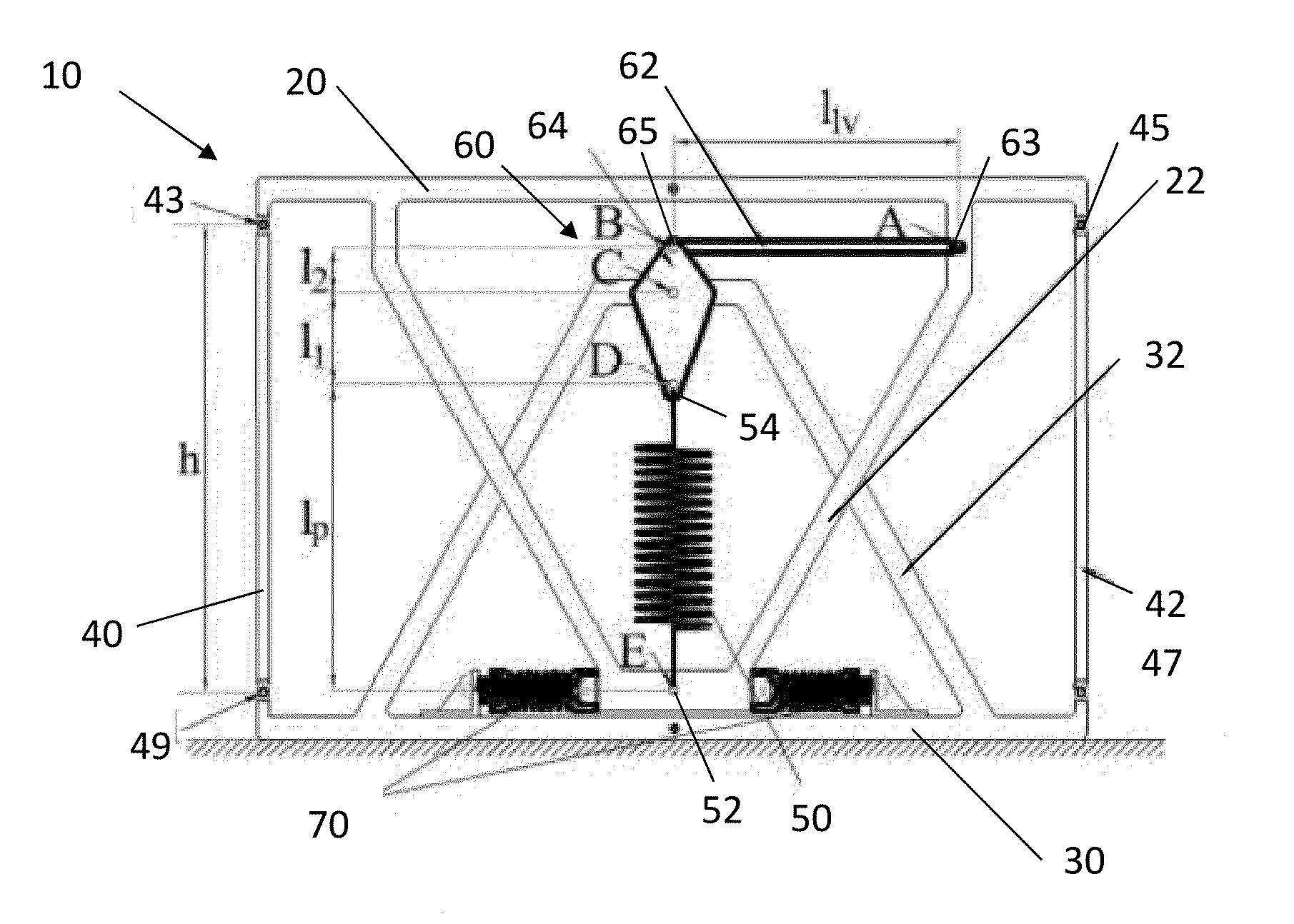
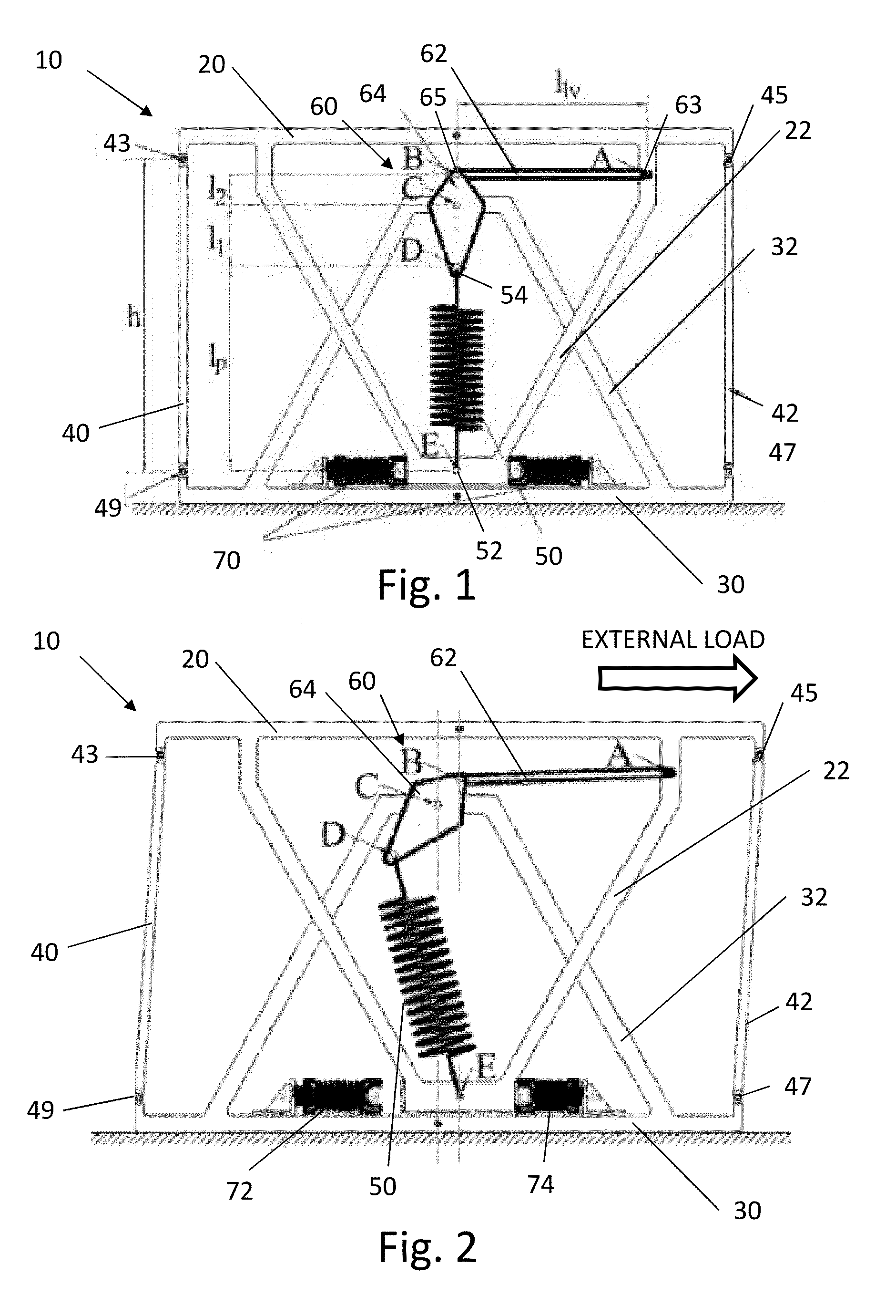
[0031]A schematic of a device 10 according to an embodiment of the present invention is shown in FIG. 1, in a rest state, and shown in FIG. 2, in an engaged state. As shown in FIGS. 1 and 2, the device 10 includes a movement frame 20 and an anchor frame 30. The movement frame 20 has an extension portion 22, which extends in the direction of the anchor frame 30. The anchor frame 30 has an extension portion 32, which extends in the direction of the movement frame 20. In the embodiment shown in FIGS. 1 and 2, the extension portions 22, 32 are chevron braces, but other brace configurations could alternatively be used. Connecting members 40, 42 pivotably connect the anchor frame 30 to the movement frame 20, for example, via hinges 43, 45, 47, 49, such that movement frame 20 is laterally translatable relative to the anchor frame 30. The connecting members 40, 42 can limit the maximum vertical distance h between the movement frame 20 and the anchor frame 30. The embodiment shown in FIGS. 1...


PUM


Abstract

A negative stiffness device and method for seismic protection of a structure is described. In one embodiment, the device has an anchor frame and a movement frame laterally translatable relative to the anchor frame. The anchor frame and movement frame have respective extension portions. A linkage is pivotably connected to the extension portion of the anchor frame. A compressed spring has a first end is attached to the extension portion of the movement frame and a second end attached to the linkage. The compressed spring has a spring force. In a rest state, the compressed spring does not apply a lateral force to the movement frame. In an engaged state, the compressed spring is configured to apply a lateral force to displace the movement frame in a lateral direction of a seismic load. The spring force is amplified by the linkage when the movement frame is laterally displaced to an amplification point.

Description

CROSS-REFERENCE TO RELATED APPLICATION[0001]This application claims the benefit of priority to U.S. provisional patent application Ser. No. 61 / 558,593 filed Nov. 11, 2011, now pending, the disclosure of which is incorporated herein by reference in its entirety.FIELD OF THE INVENTION[0002]The invention relates to apparatuses for isolating large structures and structural members from seismic forces.BACKGROUND OF THE INVENTION[0003]Systems and devices for improving structural response to earthquakes are based on the principle of seismic isolation, in which energy is generally dissipated by mechanical dissipating devices. In order to prevent damage to maintain structural components, large horizontal displacements must be accommodated. For example, passive systems have been used for this purpose, including devices having lead cores within lead-rubber bearings, frictional sliding bearings, and other supplemental mechanical energy-dissipating devices such as steel, viscous, or visco-elasti...

Claims


Application Information

Patent Timeline
IPC IPC(8): E04H9/02E04B1/98
CPCE04H9/02F16F15/00E04H9/021E04B1/98E04H9/0215E04H9/0235F16F1/121F16F1/128F16F3/04F16F2228/063
Inventor CONSTANTINOU, MICHAEL C.REINHORN, ANDREI M.SARLIS, APOSTOLOS A.TAYLOR, DOUGLASLEE, DAVID A.NAGARAJAIAH, SATISHPASALA, DHARMA THEJA R.
Owner THE RES FOUND OF STATE UNIV OF NEW YORK
Why Eureka
Try Eureka