Filter arrangement

Inactive Publication Date: 2013-05-16
IBS FILTRAN KUNST METALLERZEUGNISSE
12 Cites 15 Cited by

AI-Extracted Technical Summary

Problems solved by technology

The inventive concept can be summarized to the effect that one or more magnets are arranged in the filter housing in such a manner that they are located in regions of the filter housing in which a relativ...

Benefits of technology

[0006]The invention is therefore based on the object of improving a filter arrangement or an engine oil or transmission oil filter of the type mentioned in the introduction in this respect. I...

Abstract

A filter arrangement for the filtration of oil or an ATF fluid, in particular a transmission oil filter, has at least a first and a second filtration layer which are arranged spaced apart by at least one spacer in a filter housing to form at least one intermediate chamber. At least one magnet or a magnet arrangement for keeping iron particles out of the oil flow are provided between the first and the second filtration layers.

Application Domain

Technology Topic

Image

  • Filter arrangement
  • Filter arrangement
  • Filter arrangement

Examples

  • Experimental program(1)

Example

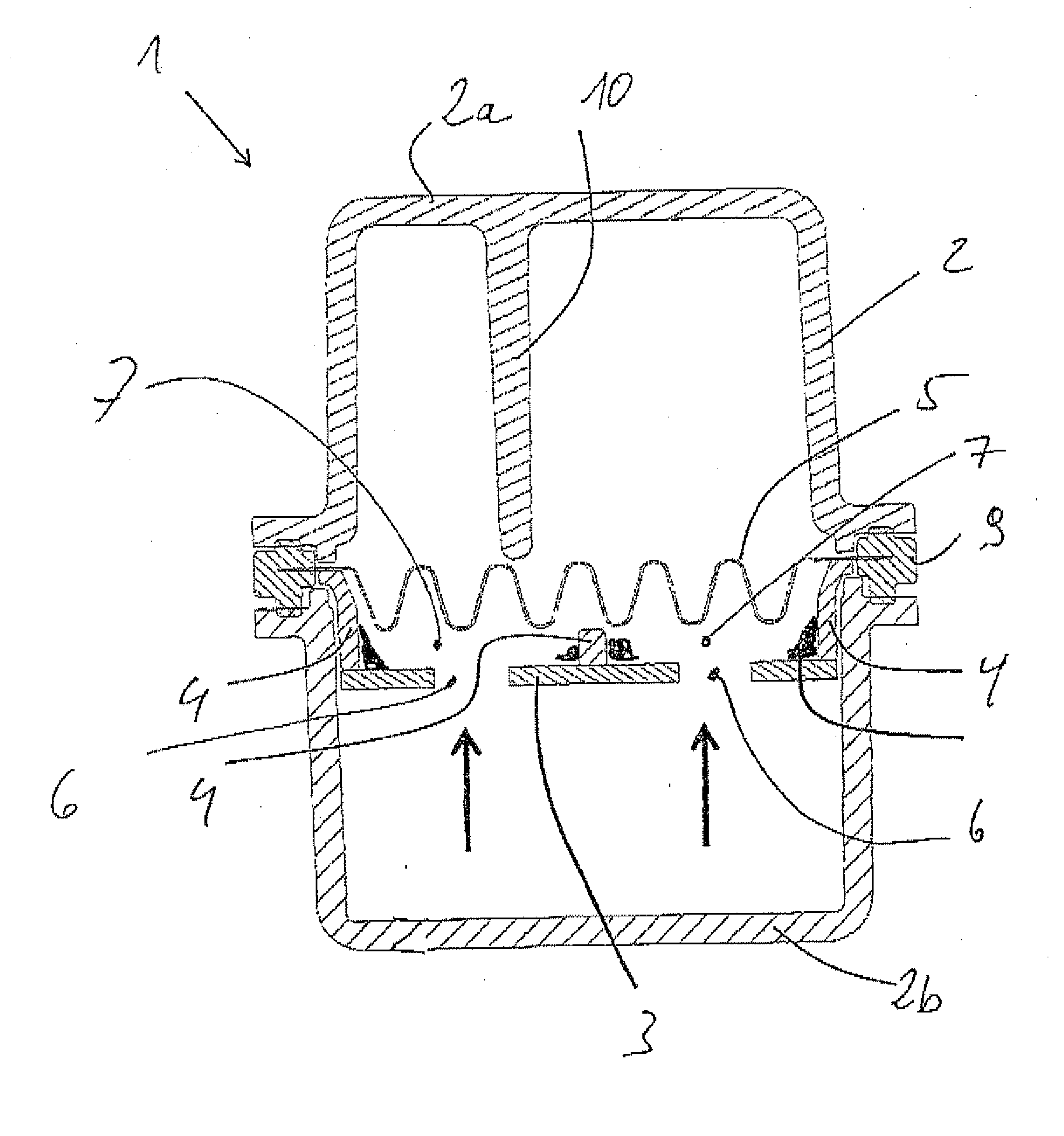
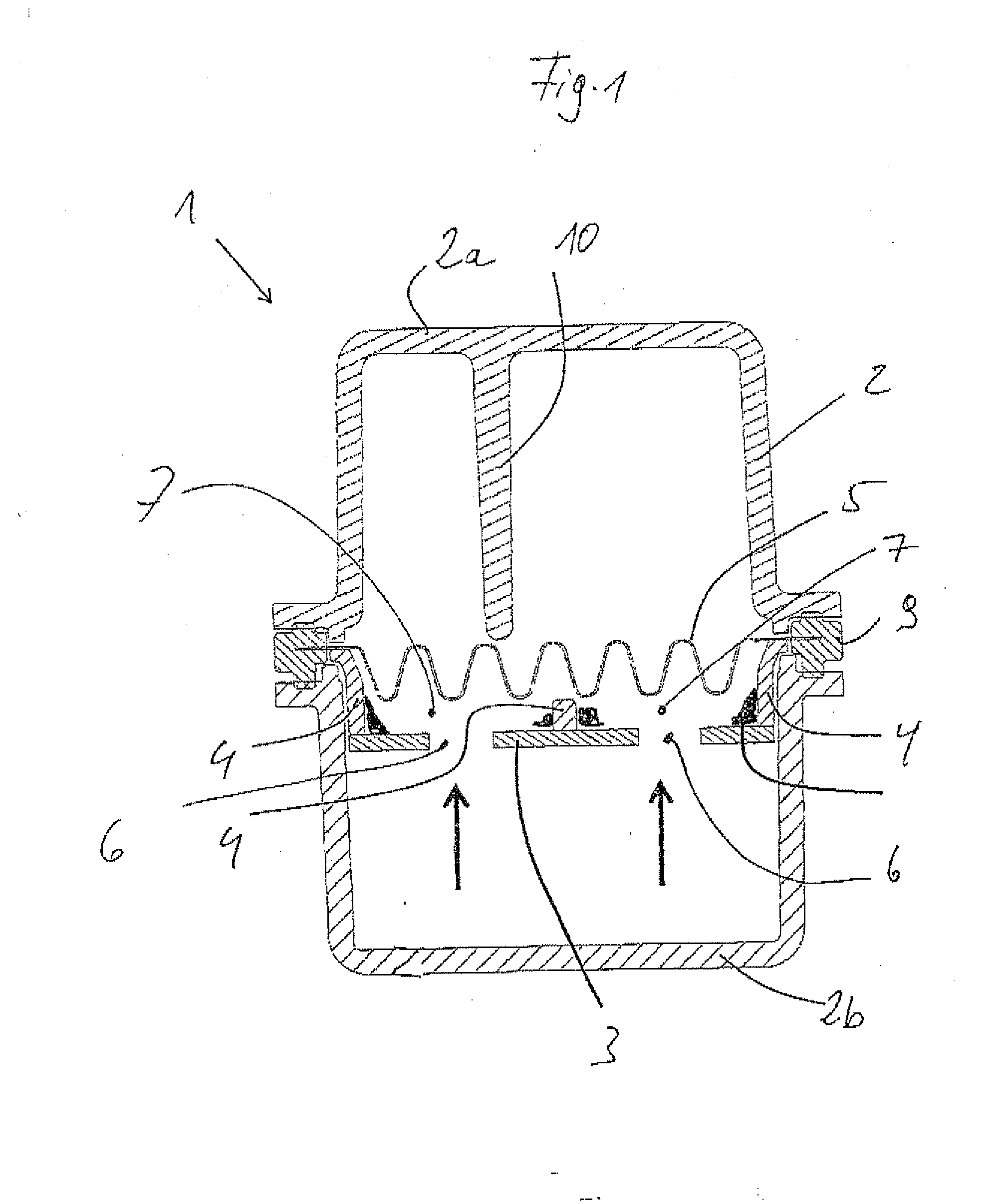
[0030]Reference is made first of all to FIG. 1, which shows a cross section through a transmission oil filter 1 according to the invention. An oil inflow and an oil outflow are not shown for reasons of simplification.
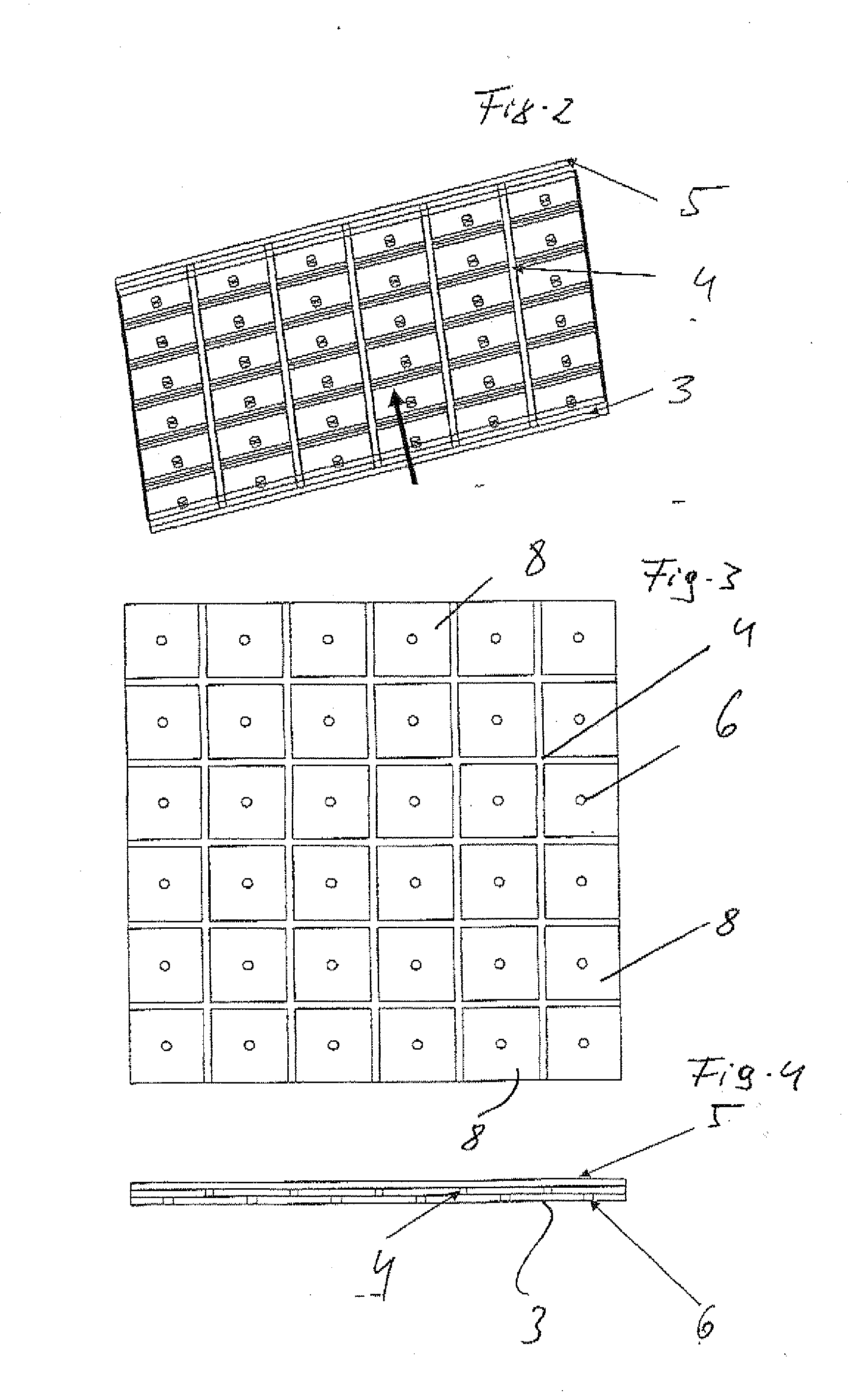
[0031]The transmission oil filter 1 comprises a filter housing 2 with two shells, an upper filter shell 2a and a lower filter shell 2b. An arrangement made up of a first filtration layer 3, a support grid 4 and a second filtration layer 5, which form a filter sandwich, extends approximately in the dividing plane of the filter housing 2.
[0032]The first filtration layer 3 in the direction of flow of the oil or of another transmission liquid (ATF) is that filtration layer which faces towards the oil flow, or the upstream filtration layer. The second filtration layer 5 is that filtration layer through which the fluid emerges.
[0033]The first filtration layer 3 can be in the form, for example, of a filter nonwoven as the ultrafine filtration medium. The second filtration layer 5 can be in the form either of a folded or planar woven filter, or of a metal screen grid.
[0034]An oil inflow or fluid inlet is provided in the lower filter shell 2b, in such a manner that the entire oil flow, as indicated by the arrows in FIG. 1, flows through the filter arrangement from sides of the first filtration layer 3. A fluid outlet is accordingly provided in the upper filter shell 2a.
[0035]As has already been mentioned in the introduction, the transmission oil filter 1 according to the invention is designed according to the “partial flow” principle. To this end, a multiplicity of flow apertures 6 formed as circular boreholes having a diameter of between 0.1 and 3 mm are provided in the first filtration layer 3. By way of the support grid 4, which is arranged downstream of the first filtration layer 3 in the direction of flow and defines an intermediate chamber or a multiplicity of intermediate chambers 7, the entire filter area is divided into a multiplicity of fields 8, in each of which the flow apertures 6 are arranged centrally.
[0036]The support grid 4 and the second filtration layer 5 are provided at the edges with a common mount 9, which is clamped between the upper filter shell 2a and the lower filter shell 2b at the edges.
[0037]As already mentioned above, the entire support grid 4 is in the form of a plastic-bonded magnet, i.e. it consists of a thermoplastic material with permanent-magnetic particles embedded therein as a matrix.
[0038]The mode of operation of the transmission oil filter 1 according to the invention is as follows:
[0039]If the fluid has a low viscosity, or if the oil has a low viscosity, the flow pressure will be transmitted virtually without any losses directly into the intermediate chambers 7 through the first filtration layer 3, which is in the form of an open filter medium. The pressure in the intermediate chambers 7 is determined by the driving jet of the dynamic pressure caused by the flow apertures 6. In this state, the dynamic pressure decisively determines the negative pressure in the intermediate chamber 7. The smaller the hole, the greater the dynamic pressure and the higher the negative pressure in the intermediate chamber 7. This negative pressure in the intermediate chamber 7 ensures that the appropriate proportion of the fluid flows through the tighter filter medium of the first filtration layer 3.
[0040]If the fluid or the oil is highly viscous, the pressure will be transmitted with a relatively small loss into the intermediate chamber 7 through the first filtration layer 3. The pressure in the intermediate chamber 7 is determined by the driving jet from the flow aperture 5 and the pressure loss in the chamber. The diameter of the flow aperture 6 decisively determines the negative pressure in the intermediate chamber 7. The smaller the flow aperture 6 and the flatter the intermediate chamber 7, the higher the overall pressure loss of the filter. In this state, the first filtration layer 3 in the form of a tighter filter medium will be virtually completely bypassed.
[0041]Irrespective of the state of viscosity of the fluid, a velocity profile is established over the cross section of the driving jet through the flow aperture which is characterized in that a relatively low flow velocity prevails at the edges of the driving jet and in the region of the mount of the support grid, but a relatively high flow velocity prevails in the centre of the flow aperture 6, such that as a result the support grid 4 is arranged in a dead flow zone by virtue of the arrangement of the flow apertures 6 in the centre of the fields 7 in relation to the driving jet passing through the flow apertures 6. In this region, relatively heavy particles transported in the fluid accumulate. Such heavy particles include, by way of example, metal particles which can adhere to the magnetic support grid 4 there.
[0042]This results in the following advantages. No additional installation space is required for magnets; instead, the installation space taken up by the support grid 4 is utilized optimally. The flow conditions between the filtration layers 3 and 5 result in optimum accumulation of particles at the edges of the support grid 4. Smaller ferromagnetic particles which would otherwise not be retained are retained in the fine filter medium.
[0043]In the case of relatively high viscosities, the particles at the edges are not torn away since the fine filter medium is bypassed and virtually no flow velocity prevails there.
[0044]In addition, what arises is a strong independence from dynamic effects of the transmission liquid, for example by waves and sloshes. This also arises as a result of the fact that the upper filter shell 2a is arranged at the top in the installed position of the transmission oil filter 1, and the lower filter shell 2b is arranged at the bottom in the installed position of the transmission oil filter 1, but any sloshing movements take place at the bottom in the installed position.
[0045]No additional components are required. Since no additional magnets are required, the weight of the transmission oil filter 1 according to the invention is reduced considerably. Additional outlay on assembly is not required. Magnets which are not additionally fitted and/or provided cannot be damaged during transportation. Commercially available permanent magnets are pressed or sintered and accordingly fragile.
[0046]The reference sign 10 denotes support ribs in the upper filter shell 2a which prevent displacement of the first filtration layer 3.
[0047]The invention has been explained above with reference to an exemplary embodiment in which the filter arrangement has two filtration layers 3, 5 arranged spaced apart, wherein the first filtration layer 3 in the direction of flow comprises a relatively open filter medium and the second filtration layer 5 in the direction of flow comprises a filter medium which is tighter and finer in relation to the first filtration layer 3.
[0048]As already described in the introduction, a perforated plate having flow apertures can also be provided as a restrictor instead of the first filtration layer 3 in the direction of flow, wherein an intermediate chamber is formed between the perforated plate and the second filtration layer. Apart from that, the perforated plate can correspond approximately to the first filtration layer 3 in geometrical terms, wherein the flow apertures in the perforated plate are larger than the flow apertures in the first filtration layer. Apart from that, a support grid corresponding in nature to the support grid according to the exemplary embodiment described above can be arranged between the perforated plate and the second filtration layer. It is clear to a person skilled in the art that the second exemplary embodiment also makes use of the principle of the invention and the advantage thereof.
LIST OF REFERENCE SIGNS
[0049] 1 Transmission oil filter [0050] 2 Filter housing [0051] 2a Upper filter shell [0052] 2b Lower filter shell [0053] 3 First filtration layer [0054] 4 Support grid [0055] 5 Second filtration layer [0056] 6 Flow apertures [0057] 7 Intermediate chambers [0058] 8 Fields [0059] 9 Mount [0060] 10 Support ribs

PUM

PropertyMeasurementUnit
Flow rate
Magnetism
tensileMPa
Particle sizePa
strength10

Description & Claims & Application Information

We can also present the details of the Description, Claims and Application information to help users get a comprehensive understanding of the technical details of the patent, such as background art, summary of invention, brief description of drawings, description of embodiments, and other original content. On the other hand, users can also determine the specific scope of protection of the technology through the list of claims; as well as understand the changes in the life cycle of the technology with the presentation of the patent timeline. Login to view more.

Similar technology patents

Traditional Chinese medicine decoction device

ActiveCN105287216AReduces the risk of inconsistent decoction quality or drug mix-upsSave installation spacePharmaceutical product form changeDomestic articlesMedicinal herbsEngineering
Owner:永春县产品质量检验所福建省香产品质量检验中心国家燃香类产品质量监督检验中心福建

Emergency rescue vehicle

PendingCN107653920ARealize collaborative workSave installation spaceMechanical machines/dredgersEndless track vehiclesEngineeringEmergency rescue
Owner:JIANGSU XCMG CONSTR MASCH RES INST LTD

Classification and recommendation of technical efficacy words

Why Eureka
Try Eureka