Proximity sensor assembly and inspection system

Active Publication Date: 2013-05-16
BAKER HUGHES INC
View PDF6 Cites 8 Cited by
  • Summary
  • Abstract
  • Description
  • Claims
  • Application Information

AI Technical Summary

Benefits of technology

The patent describes a proximity sensor that can be placed in narrow spaces around an object. It has a small, flat design and can be attached to a substrate using a cable that runs parallel to the substrate and perpendicular to the sensor's electromagnetic field. The technical effect of this design is that it allows for accurate sensing in tight spaces and can easily be inserted into narrow spaces around a target object.

Problems solved by technology

Also, in some applications, the cylindrical proximity sensor cannot be used where a hole cannot be drilled or a bracket cannot be installed to mount the proximity sensor.

Method used


Image

  • Proximity sensor assembly and inspection system
  • Proximity sensor assembly and inspection system
  • Proximity sensor assembly and inspection system

Examples


Embodiment Construction

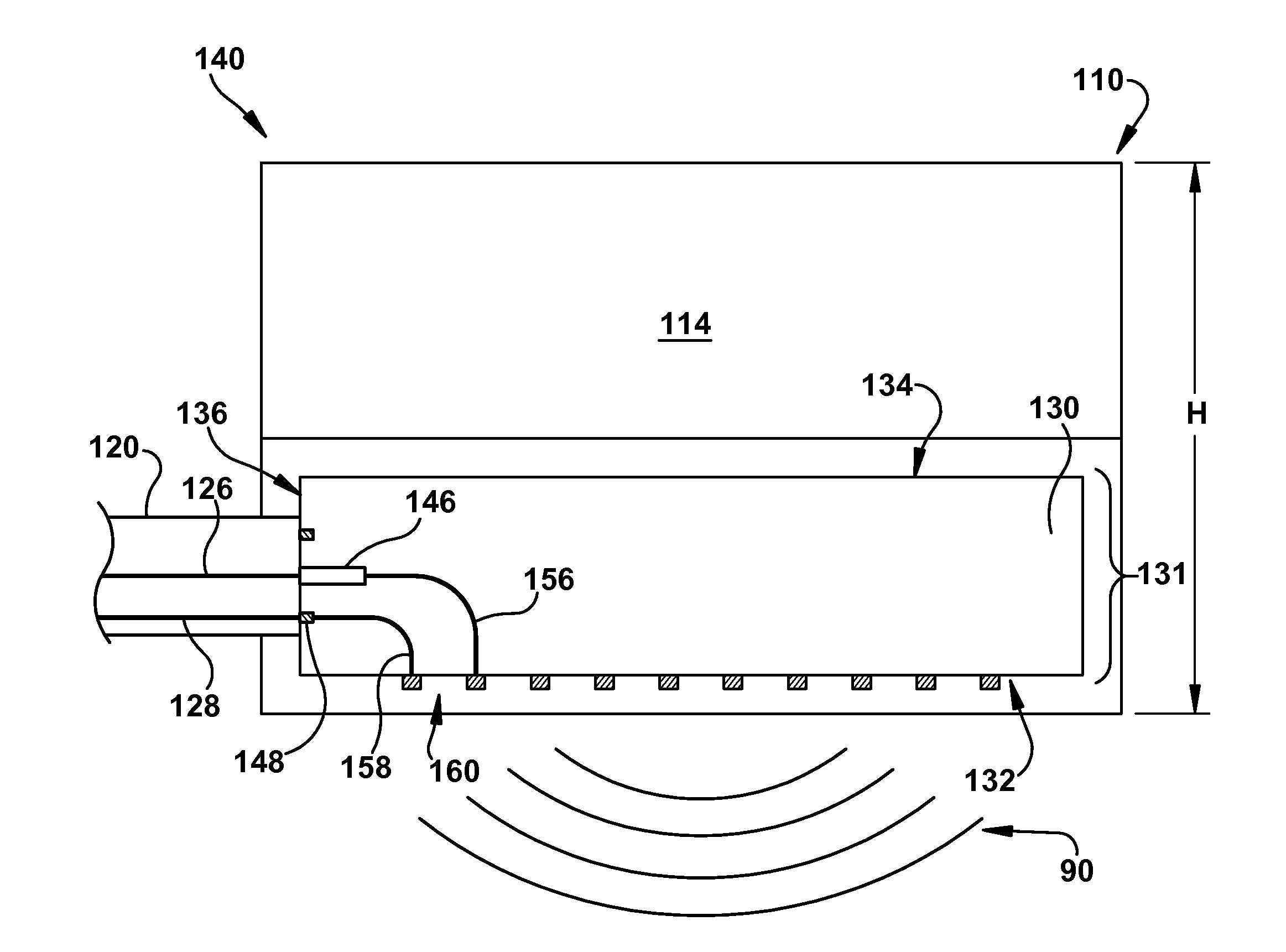
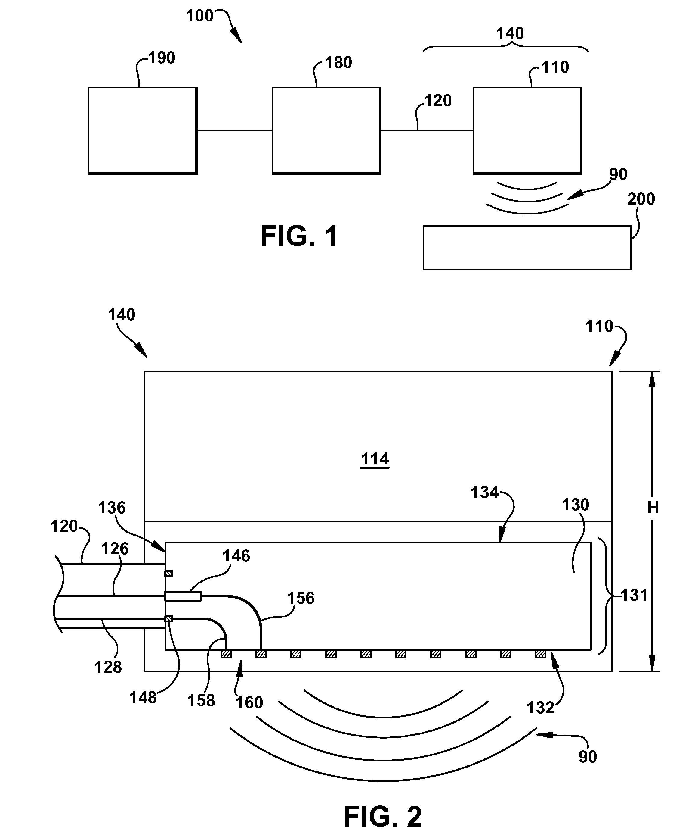
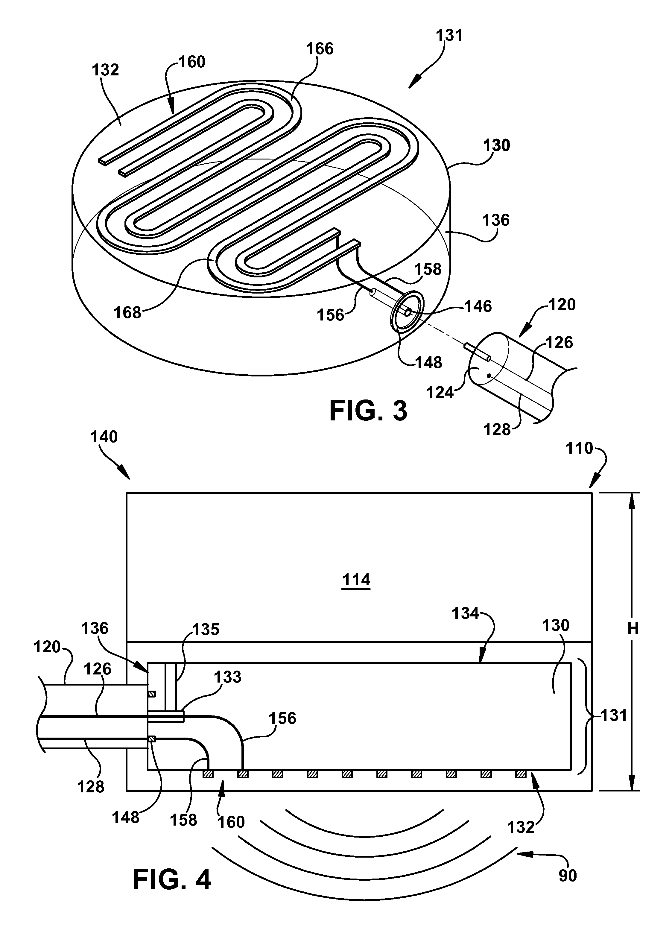
[0014]FIG. 1 is a diagram of an exemplary inspection system 100 that can measure, monitor, and inspect an object 200 (e.g., a turbine component). The inspection system 100 comprises a proximity sensor 110 connected by a cable 120 to a signal generation and processing component 180, which can be connected to a diagnostic monitor 190. The proximity sensor 110 and cable 120 are collectively referred to herein as a proximity sensor assembly 140.

[0015]The signal generation and processing component 180 outputs an electrical driving signal to the proximity sensor 110 that causes the proximity sensor 110 to generate an electromagnetic field 90 that projects away from the proximity sensor 110. In one embodiment, the electrical driving signal is a signal having a frequency in the microwave range, and is also referred to herein as a microwave driving signal. As used herein, the term “microwave” refers to electrical signals with frequencies of about 300 MHz or greater and, in one example, from ...


PUM


Abstract

A proximity sensor assembly with a sensing element having a substrate and an antenna pattern disposed on one or more planar surfaces of the substrate is disclosed. The cable is fed substantially parallel to the planar surfaces of the substrate and is attached to the side surface of the substrate, such that the cable is oriented substantially perpendicular to the direction of the electromagnetic field emitted from the sensing element.

Description

BACKGROUND OF THE INVENTION[0001]The subject matter disclosed herein relates to a proximity sensor assembly and inspection system.[0002]Proximity sensors, including eddy current sensors, magnetic pick up sensors, and capacitive sensors, can be used to monitor the vibration, movement, or other operational characteristics of a machine (e.g., a turbine) by measuring the distance between the proximity sensor and the machine. In an example of dynamic detection, a proximity sensor can be used to detect the frequency of the vibration of a machine component (e.g., vibration of the rotating shaft of a turbine) by monitoring any changes in the position of a machine component relative to the proximity sensor as the machine component vibrates. In an example of static detection, a proximity sensor can be used to detect the expansion of a machine component as it warms up and expands, causing the machine component to move closer to the proximity sensor, or to measure the contraction of a machine c...

Claims


Application Information

Patent Timeline
IPC IPC(8): G01R27/04
CPCF02C9/00F01D17/20F01D11/06H03K17/945G08B13/2491G01B7/023G01B7/14G01B15/00
Inventor SHEIKMAN, BORIS LEONIDGO, STEVENWHITELEY, JOSEPH LEEWELLER, NATHAN ANDREWROUSH, SUSAN LEELEE, YONGJAE
Owner BAKER HUGHES INC
Why Eureka
Try Eureka