Semi-portable emergency cooling system for removing decay heat from a nuclear reactor

a nuclear reactor and emergency cooling technology, applied in nuclear engineering, nuclear elements, greenhouse gas reduction, etc., can solve the problems of increasing the cost of shutdown operation, not having sufficient cooling capacity to remove the high level of residual heat generated, and affecting the efficiency of the shutdown operation

Active Publication Date: 2013-05-16
WESTINGHOUSE ELECTRIC CORP
View PDF10 Cites 21 Cited by
  • Summary
  • Abstract
  • Description
  • Claims
  • Application Information

AI Technical Summary

Problems solved by technology

The heat removal capacity of this system is necessarily large.
This is due to the fact that the spent fuel pool, the eventual storage place for the fuel, has a permanently installed cooling system, which does not have sufficient cooling capacity to remove the high level of residual heat generated by the fuel immediately following plant shutdown.
This cool down time increases the facility's overall shutdown period, thus increasing the cost of the shutdown operation, resulting in lost revenues, as well as the cost of replacement power purchased during the shutdown.
On the other hand, the cost of such an auxiliar

Method used


Image

  • Semi-portable emergency cooling system for removing decay heat from a nuclear reactor
  • Semi-portable emergency cooling system for removing decay heat from a nuclear reactor
  • Semi-portable emergency cooling system for removing decay heat from a nuclear reactor

Examples


Embodiment Construction

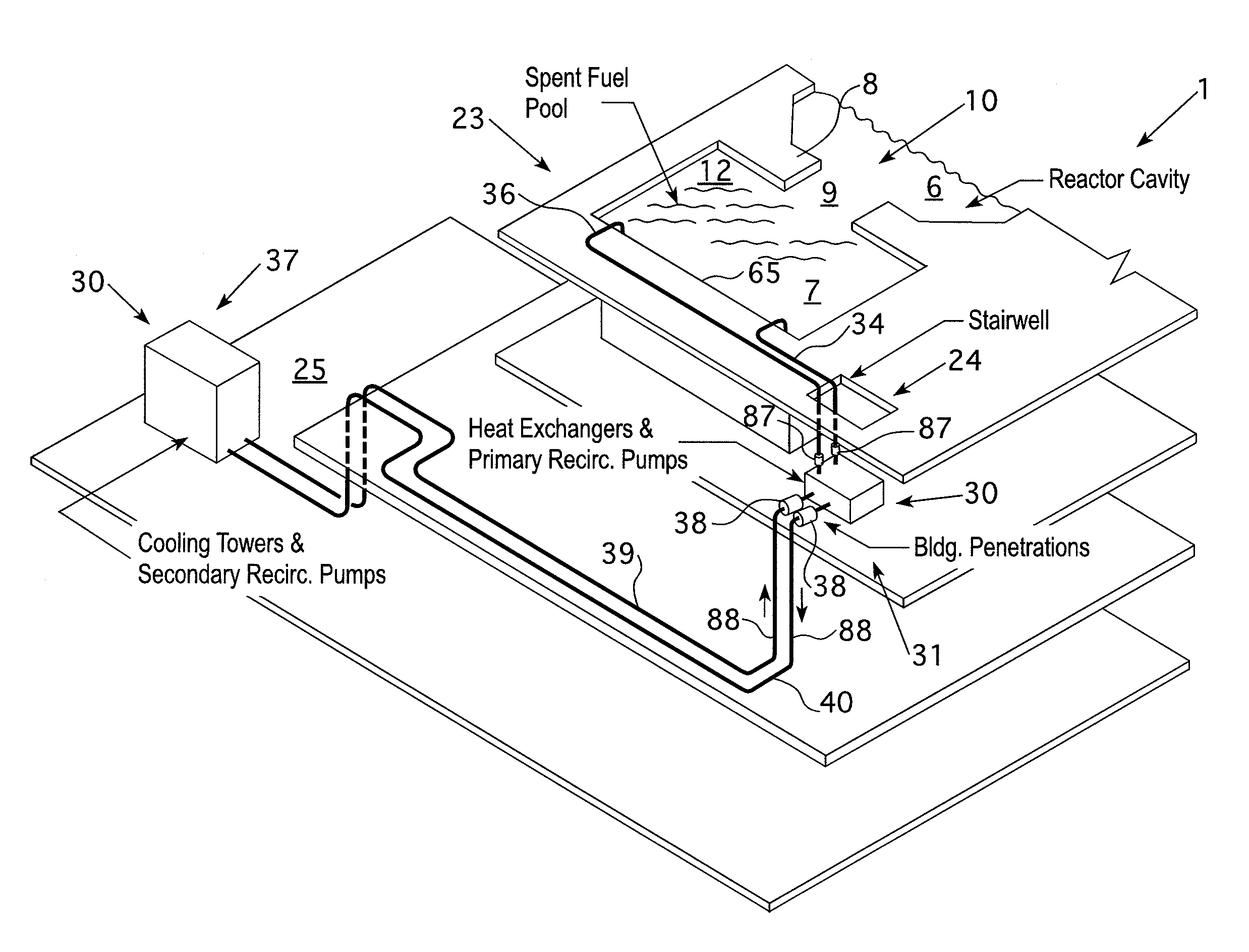
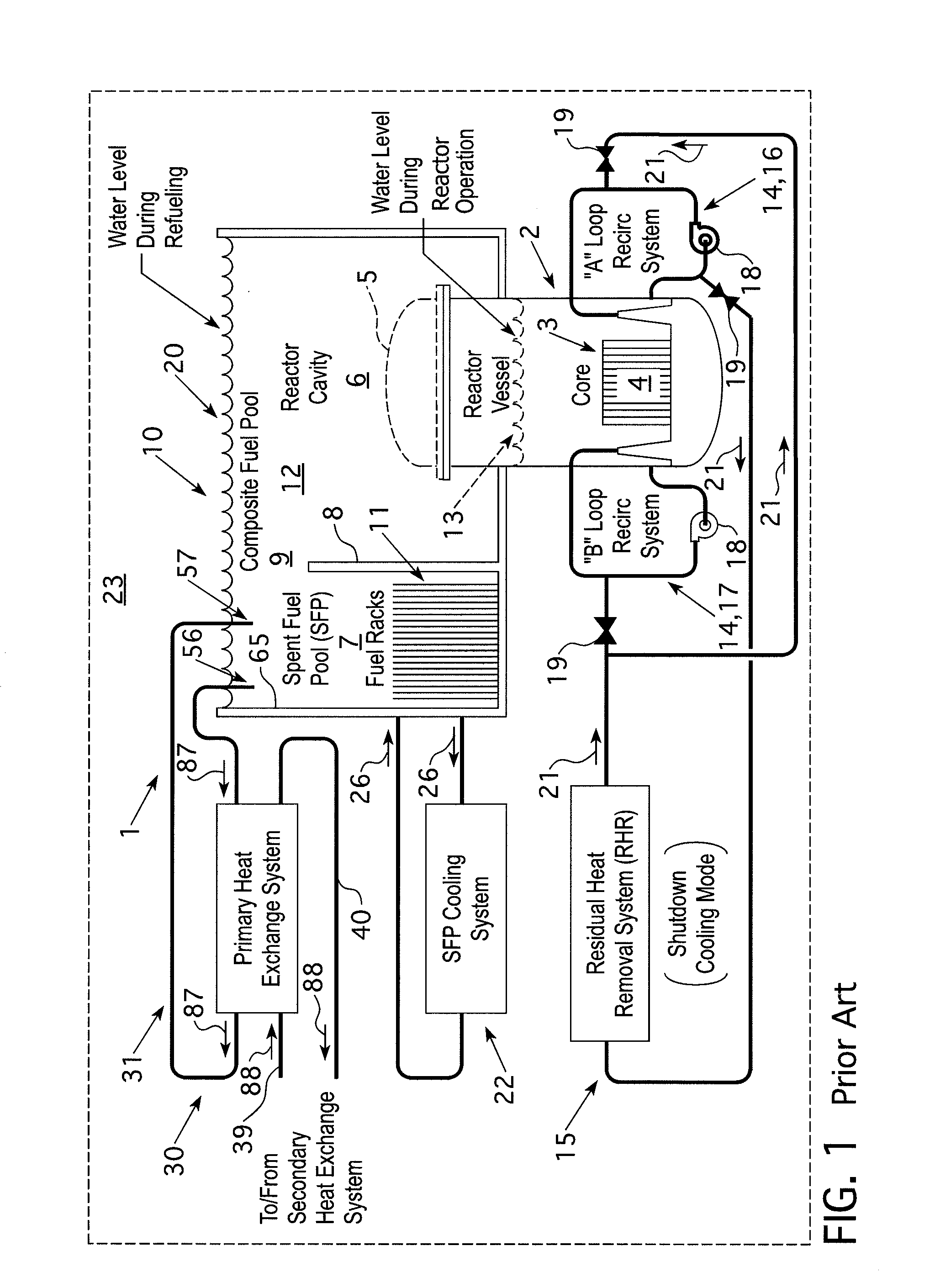
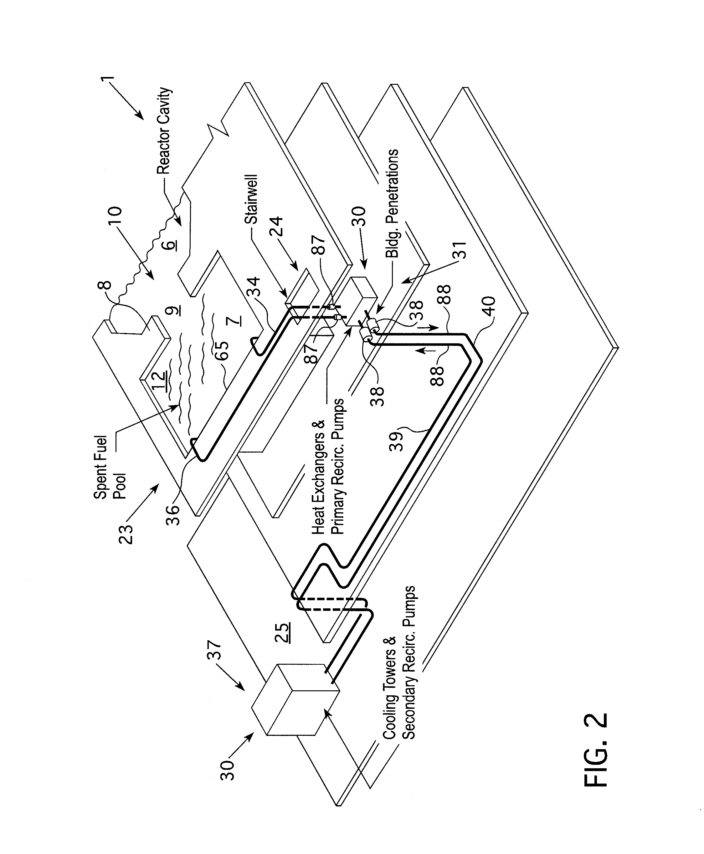
[0020]As shown in FIG. 1, in a typical nuclear power generating facility 1, only the pertinent parts of which are shown, a reactor building 23 contains a reactor vessel 2, which contains a core 3, which comprises numerous elements of nuclear fuel 4, usually in the form of fuel bundles, commonly referred to as fuel assemblies. During power generating operations reactor vessel 2 is closed by the top or head 5. Reactor vessel 2 is positioned within a reactor cavity 6 (shown in FIGS. 1 and 2), which is fluidly connected to a spent fuel pool 7 during outages. In the facility embodiment shown in FIGS. 1 and 2, the spent fuel pool 7 is separated from the reactor cavity by a wall 8 having a closable opening 9, closable by a gate (not shown) or other means known in the art to isolate the spent fuel pool 7 from the reactor cavity 6. Since various embodiments of nuclear power generating facilities 1 are possible, the spent fuel pool 7 and the reactor cavity 6 will be jointly and separably refe...


PUM


Abstract

An emergency temporary spent fuel pool cooling system for a nuclear power generating facility that has a permanently installed primary loop within the nuclear containment and a mobile temporary secondary loop. The secondary loop is housed in transport vehicles that can be stored off site and is connectable in heat exchange relationship with the primary loop through quick disconnect couplings that are accessible on the outside of the reactor containment. The transport vehicles also include self-contained power and compressed air sources for powering and controlling the entire emergency cooling system. The system also has a make-up water injection capability for refueling the spent fuel pool and secondary loop.

Description

CROSS REFERENCE TO RELATED PATENTS[0001]This application is an improvement on U.S. Pat. No. 5,268,942, issued Dec. 7, 1993 and assigned to the Assignee of this application.BACKGROUND[0002]1. Field[0003]This invention relates generally to cooling systems used to cool water in a nuclear reactor power generating facility and, more particularly, to a temporary cooling system which is designed to supplement existing cooling systems and accommodate emergency conditions experienced in such a facility.[0004]2. Related Art[0005]In nuclear power generating facilities, a reactor vessel housing nuclear fuel and water is positioned in what is commonly referred to as a refueling cavity or a reactor cavity. During power generation, a primary fluid coolant, normally water, is heated by the nuclear fuel, and the heat is used to generate steam for electric power generation. During shutdowns for refueling and other periods when the reactor is not operating, the decay heat from the fuel continues to he...

Claims


Application Information

Patent Timeline
IPC IPC(8): G21C15/18
CPCG21C15/182Y02E30/40G21D3/04G21D1/02Y02E30/00Y02E30/30
Inventor NEWTON, PETER M.WILSON, DAVID W.PARKE, JOHN M.WADE, JAMES M.
Owner WESTINGHOUSE ELECTRIC CORP
Why Eureka
Try Eureka