
Anchoring device

a technology of an anchoring device and a ring, which is applied in the direction of rod connections, couplings, mechanical apparatuses, etc., can solve the problems of additional components, additional components, and the need to hold the shell halves or wedges together by additional components

Inactive Publication Date: 2013-05-16
ILLINOIS TOOL WORKS INC
View PDF4 Cites 7 Cited by
  • Summary
  • Abstract
  • Description
  • Claims
  • Application Information

AI Technical Summary

Benefits of technology

The patent describes a drilling assembly that can prevent the expansion elements from moving radially or circumferentially during use. This prevents the drill head from moving within the borehole and ensures a stable drilling process. The assembly also allows for easy removal of the drill head from the borehole by rotating the shaft and drill head in opposite directions, which causes the expansion elements to displace and provide frictional contact with the internal surface of the borehole. This results in a more secure and stable drilling process.

Problems solved by technology

However, a disadvantage of this configuration is that the shell halves or wedges need to be held together by additional components, such as studs which extend through holes in the shell halves.
The studs do not provide a robust means for connection and the additional components increase the cost of manufacture and assembly time.
Also, this rock bolt embodiment is not self drilling and requires a pre-drilled hole before the rock bolt can be inserted increasing the installation time.
Further, the rock bolt may not be easily re-configured for self drilling as the studs holding the wedges are unlikely to withstand the rotational forces of a drilling operation potentially leading to destruction of the rock bolt during that operation.
Like U.S. Pat. No. 5,219,248, a disadvantage of this configuration is that the wedging member is secured by an additional component, in this case a (preferably frangible) band or strap which permits sliding movement of the wedge.
This band is unlikely to be of a sufficient strength to retain the wedge member in position during a self drilling rock bolt operation (leading to destruction of the wedging element).
Additional components such as the band also increase both the cost of manufacture and assembly time, and complexity of use.
As discussed above, a disadvantage of these conventional types of rock bolts is that a borehole needs to be drilled before the rock bolt can be inserted and secured within the rock or coal face.
A disadvantage of this rock anchor is that for the resin to work, it has to be fast-setting.
This is not particularly suitable for coal faces as the resin in action can generate sufficient heat to cause a fire.
Further only a limited amount of material that can be applied by the integrated adhesive cartridge leading to a weak bond.
A disadvantage of this configuration is that the expansion elements or wedges are connected by a band of material to the shaft.
This configuration does not provide a robust means for connection and hence a weak mechanical set.
Also, additional components (such as the band) increase the cost of manufacture and assembly time and complexity of use.
Again, a disadvantage of this configuration is that the expansion elements or wedges are connected by a band of material to the shaft.
This configuration does not provide a robust means for connection and hence a weak mechanical set (leading to the need for an additional, chemical set).
Also, additional components (such as the band) increase the cost of manufacture and assembly time, and the complexity of use.
Furthermore, as with other chemically set rock bolts, this type of rock bolt may not be suitable for use in the coal mining industry as a fast setting chemical resin can generate sufficient heat to cause a fire as aforesaid.

Method used


Image

  • Anchoring device
  • Anchoring device
  • Anchoring device

Examples


Embodiment Construction

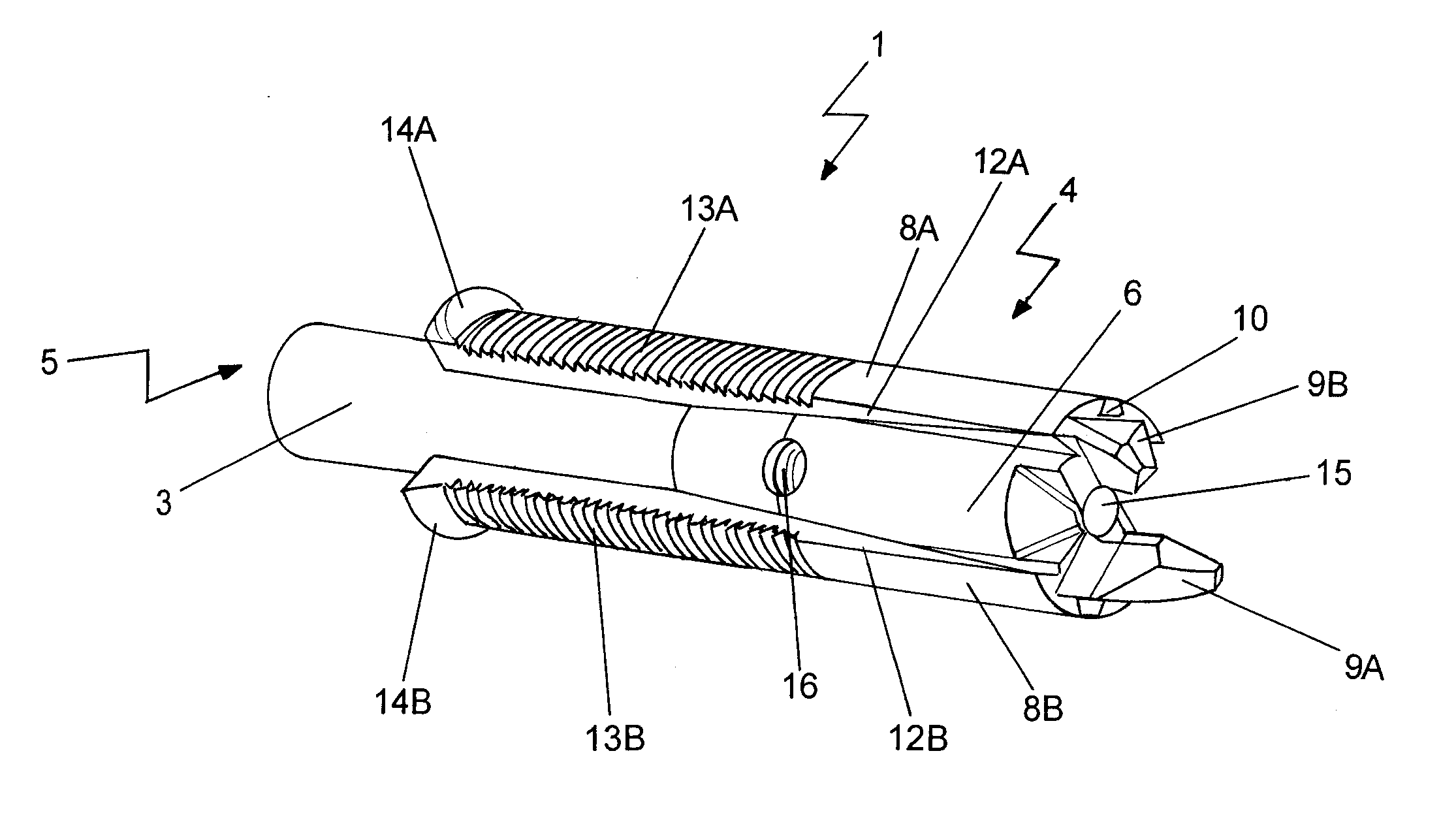
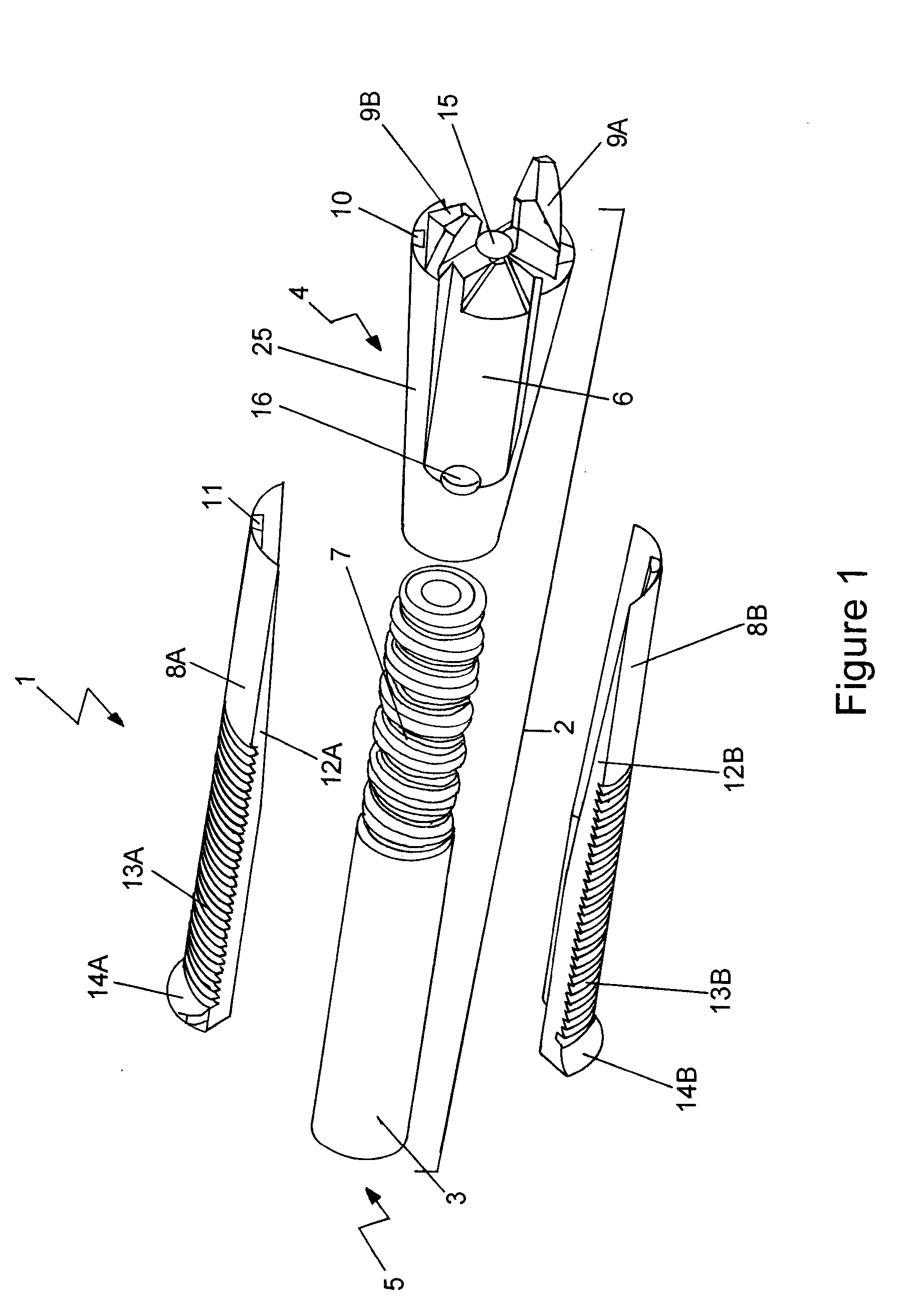
[0108]FIG. 1 shows a preferred embodiment of an anchoring device in the form of a rock bolt (1) of the present invention in its unassembled form.

[0109]Rock bolt (1) incorporates a drilling assembly (2) which includes an elongate shaft (3) with a first (drilling) end (4) and a second (drive) end (5), a drill head (6) at the first end (4), and the second end (5) being configured for connection to a drilling apparatus (not shown) in known fashion.

[0110]The shaft (3), which is typically manufactured from steel, is a hollow tube and incorporates a left hand thread (7) along a length of the shaft (3). For clarity, part of the shaft (3) in FIG. 1 is shown without the thread.

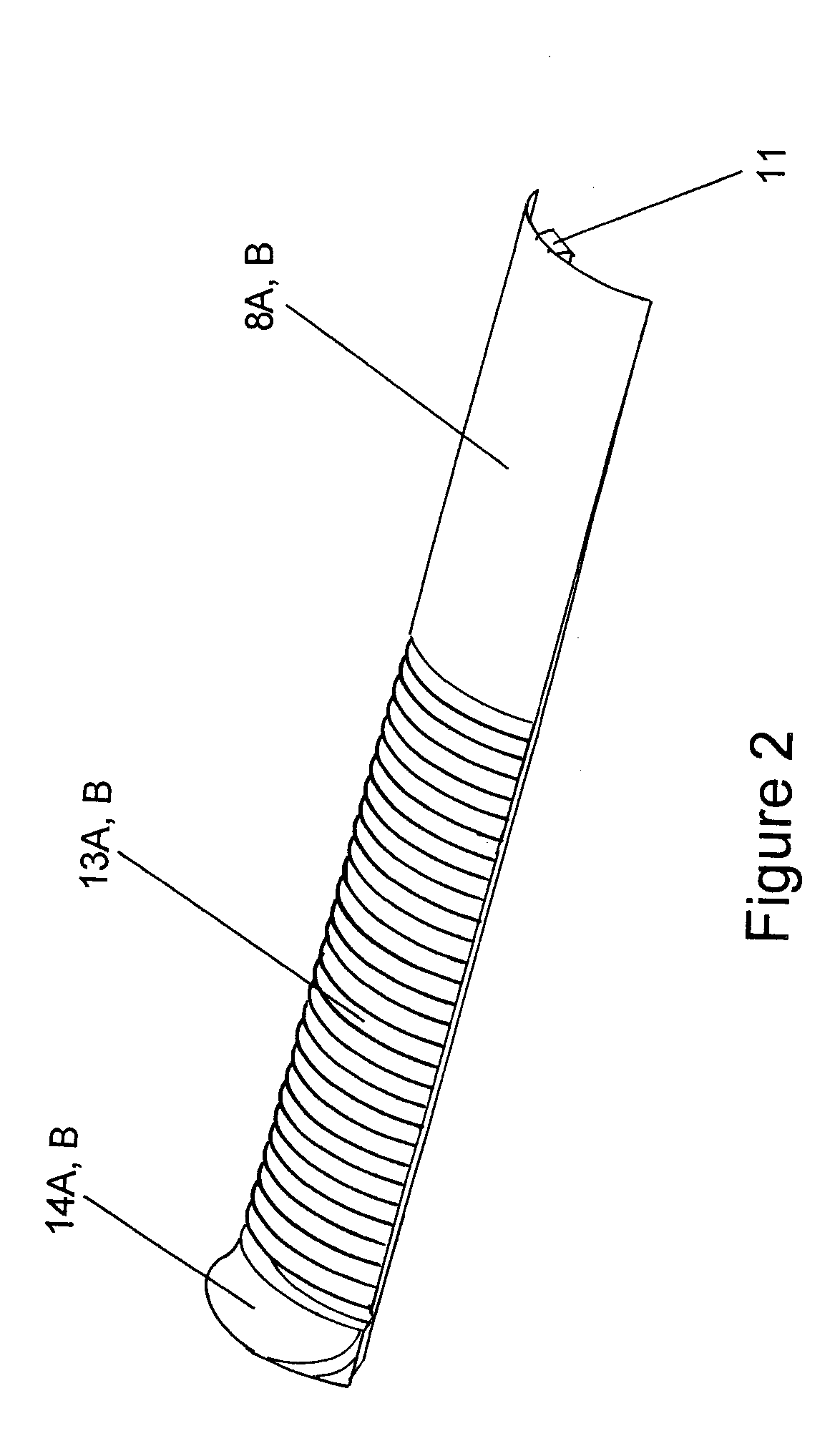
[0111]The rock bolt (1) includes expansion elements or wedges (8A, 8B). For ease of reference the expansion elements (8A, 8B) will now simply be referred to as “wedges” throughout this specification.

[0112]Wedges

[0113]With reference to FIGS. 1, 2 and 3, the wedges (8A, 8B) include ridges (13A, 13B) on the upper surface w...


PUM


Abstract

In an anchoring device, a drill head and expansion element(s) are configured to cooperatively interlock with each other to provide for directed movements of the drill head relative to a longitudinal axis of the shaft. Co-operating contact surfaces between the drill head and the expansion element(s) are configured such that relative longitudinal movement of the drill head with respect to the expansion element(s) displace(s) the expansion element(s) outwardly so the expansion element(s) can provide frictional contact with a borehole once inserted therein.

Description

TECHNICAL FIELD[0001]This invention relates to an anchoring device.[0002]In particular, the present invention relates to anchoring devices in the form of rock bolts and a method for installing rock bolts and in particular to rock bolts suitable for use in the mining and tunnelling industry to provide roof and wall support. The invention has been developed primarily for rock bolts used in mining applications and will be described hereafter with reference to this application.[0003]However, it will be appreciated that the invention is not limited solely to mining applications. For example, other materials and applications may include coal, concrete, dams, retaining walls, civil engineering, building construction and the like.BACKGROUND ART[0004]Rock bolts are now a common apparatus used to support the roof and walls of tunnels and mines worldwide. There are a wide variety of rock bolts available including steel, fibreglass and plastic rock bolts. Rock bolts usually consist of a long el...

Claims


Application Information

Patent Timeline
Patent Type & Authority Applications(United States)
IPC IPC(8): E21D21/00E21D20/00
CPCE21D21/00E21D20/00Y10T403/32254E21D2021/0053Y10T403/32E21D21/008E21D21/0053
Inventor GILMOUR, ROYDON JOHN
Owner ILLINOIS TOOL WORKS INC
Learn More