Turbine assembly

a turbine engine and rotor technology, applied in the direction of machines/engines, stators, liquid fuel engines, etc., can solve the problem of reducing the life of the rotor

Active Publication Date: 2015-06-30
GE INFRASTRUCTURE TECH INT LLC
View PDF6 Cites 17 Cited by
  • Summary
  • Abstract
  • Description
  • Claims
  • Application Information

AI Technical Summary

Benefits of technology

[0004]According to another aspect of the invention, a turbine assembly includes a rotor wheel, a circumferential slot formed in the rotor wheel configured to receive blades, and first and second ring members positioned in the circumferential slot, the first and second ring members located on each side of a portion of a blade to prevent radial movement of the blade when positioned in the circumferential slot.

Problems solved by technology

Thus, the notch opening can be a source of stress concentration in the rotor wheel and can lead to reduced rotor life.

Method used


Image

  • Turbine assembly
  • Turbine assembly
  • Turbine assembly

Examples


Embodiment Construction

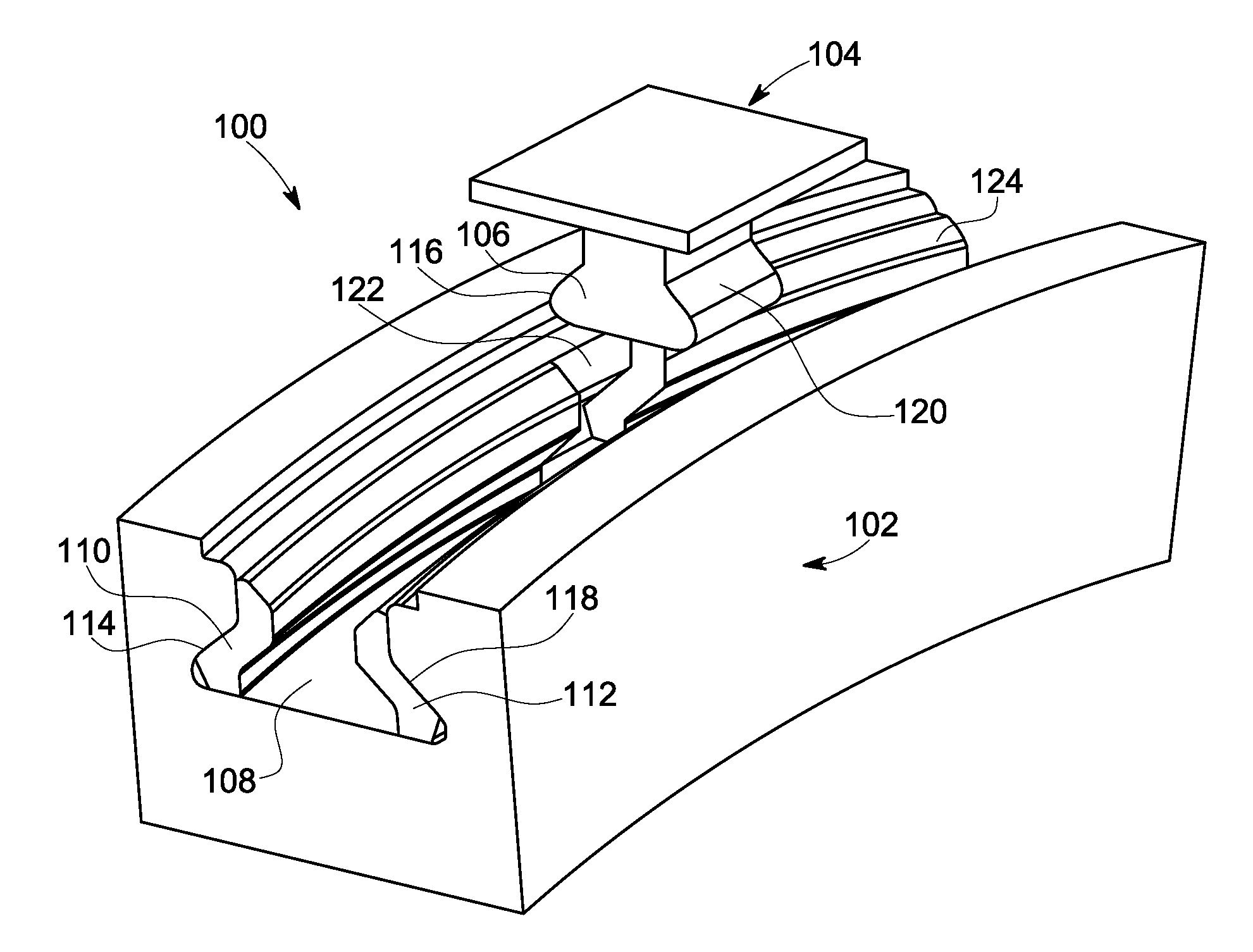
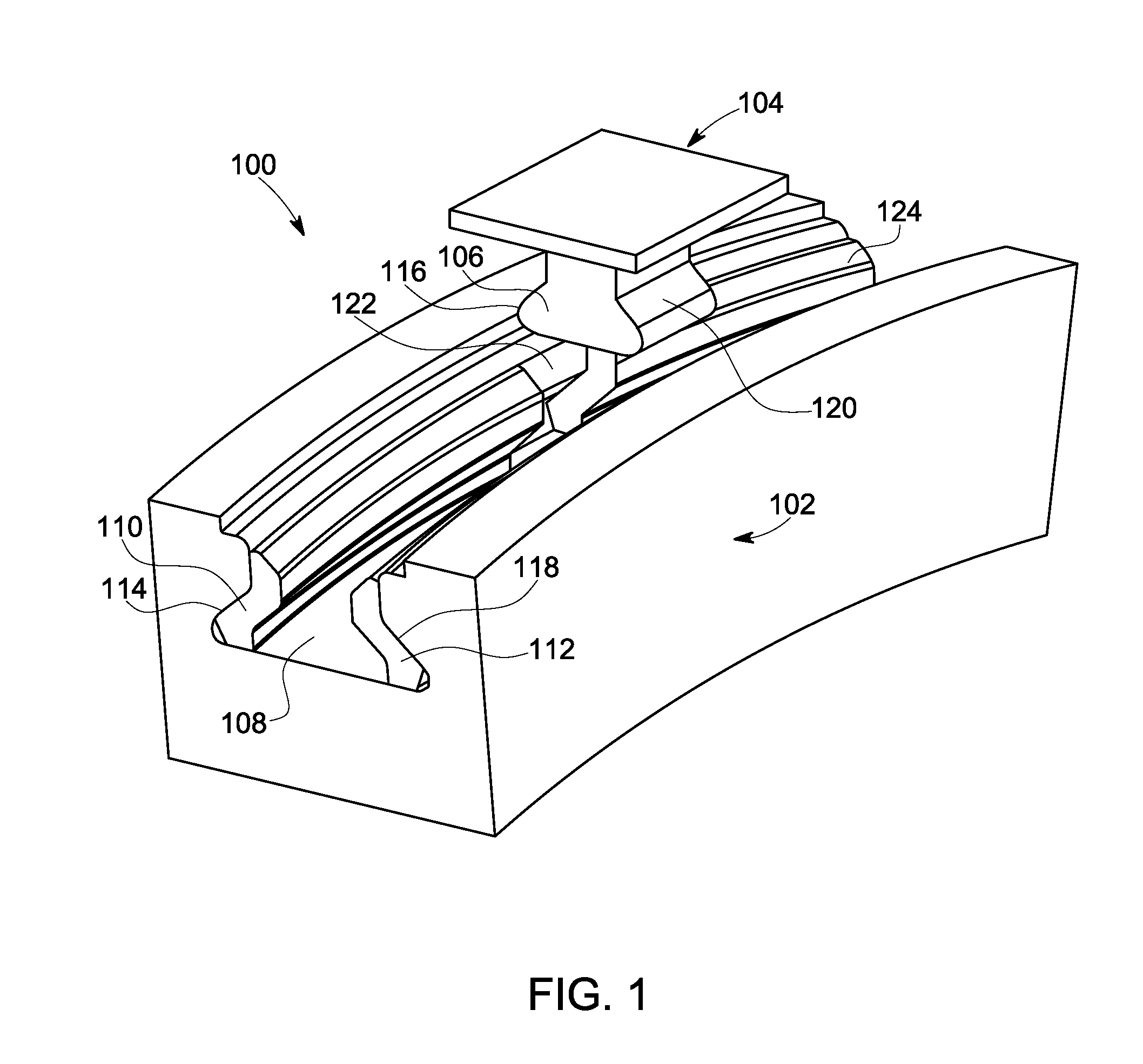
[0013]FIG. 1 is a perspective view of a portion of an exemplary turbine assembly 100 including a rotor wheel 102 configured to receive a blade 104. The blade 104 includes a dovetail pin or attachment 106 that is positioned in a circumferential slot 108 of the rotor wheel 102. In an embodiment, a first ring member 110 and a second ring member 112 are placed in the circumferential slot 108 and are configured to retain the blade 104 and prevent radial movement of the blade 104 when placed in the circumferential slot 108. In one embodiment, the rotor wheel 102 has the first ring member 110 and second ring member 112 in the circumferential slot 108 prior to installation of blades, including the blade 104. The ring members can be inserted radially into the slot and slid axially to mate with the wheel side face forming the circumferential slot 108. When positioned in the circumferential slot 108, the first ring member 110 and second ring member 112 form an opening 122 enables insertion of ...


PUM


Abstract

According to one aspect of the invention, a turbine assembly includes a rotor wheel and a circumferential slot formed in the rotor wheel, the circumferential slot including a uniform cross-section shape for a circumference of the rotor wheel. The assembly also includes a first ring member positioned in the circumferential slot, the first ring member being configured to prevent radial movement of a dovetail attachment when positioned in the circumferential slot, wherein the dovetail attachment is part of a turbine blade.

Description

BACKGROUND OF THE INVENTION[0001]The subject matter disclosed herein relates to turbine engines and, more particularly, to rotor assemblies for turbine engines.[0002]Turbine blades or buckets are often designed for installation on a turbine rotor wheel in a circumferential direction. The buckets are typically attached to the turbine wheel using external circumferential dovetails, with a receiving dovetail in a circumferential groove or slot on the wheel periphery and a complimentary dovetail in the base or root of the bucket. In order to load these buckets onto the wheel, a notch which locally removes the receiving dovetail portion is cut on the periphery of the wheel, leaving a generally rectangular opening in the slot on the rotor wheel. Each bucket is then initially placed in the notch opening and then moved circumferentially around the wheel. The opening in the circumferential groove causes a discontinuity in the relatively uniform rotor wheel design. Thus, the notch opening can...

Claims


Application Information

Patent Timeline
Patent Type & Authority Patents(United States)
IPC IPC(8): F01D5/30F01D5/32
CPCF01D5/3038F01D5/32
Inventor KENY, MAYUR ABHAYCASANOVA, FERNANDO JORGERAJENDRAN, PRATHAP RAJ
Owner GE INFRASTRUCTURE TECH INT LLC
Why Eureka
Try Eureka