Gas turbine engine blade mounting arrangement

a technology for gas turbine engines and blades, which is applied in the direction of liquid fuel engines, marine propulsion, and vessel construction, etc., can solve the problems of engine rotor slow turning, damage to fan blade root portions and slots, and add to engine cost and weight, so as to reduce the radial movement of blade root. , the effect of simple and economical

Active Publication Date: 2013-12-31
RTX CORP
View PDF11 Cites 17 Cited by
  • Summary
  • Abstract
  • Description
  • Claims
  • Application Information

AI Technical Summary

Benefits of technology

[0007]In accordance with the present invention, a lightweight, simple and economical leaf spring spacer is disposed between a radially innermost end of a gas turbine engine blade root such as a fan blade root and an adjacent radially innermost surface of a hub slot which accommodates that root. The spacer is held in place by an interference fit between the blade root and the slot such that the spacer exerts a radially outward force on the blade root to secure the blade root within the slot thereby limiting unwanted radial movement and tilting of the blade root within the slot during such conditions as windmilling of the gas turbine engine rotor. In an exemplary embodiment, the blade comprises a fan blade. Also in the exemplary embodiment, the blade root is dovetail shaped, including a pair of radially inner and outer angularly offset longitudinally extending side surfaces, and the slot includes a pair of radially inner and outer angularly offset longitudinally extending side surfaces which are opposed to the radially inner and outer side surfaces of the blade root. The leaf spring spacer is compressed between the radially innermost surfaces of the blade root and the slot which accommodates the root exerting a radially outward force on the root which causes the radially outer side surface of the blade root to bear against the radially outer side surface of the slot, thereby preventing radial movement of the blade root within the slot during the aforementioned windmilling conditions.
[0008]According to an aspect of the present invention, a mounting arrangement for a gas turbine engine blade is provided. The mounting arrangement includes a radially directed axis and a radially inner root received within a slot in an associated blade hub. The mounting arrangement also includes an elongate resilient leaf spring spacer received within said slot between a radially innermost end of said blade root and a radially innermost surface of said slot by interference fit therebetween such that said spacer exerts a radially outward force on said blade root to reduce radial movement of said blade root within said slot.

Problems solved by technology

However, when the engine is not in use, wind acting on the fan blades can cause the engine's rotor to slowly turn.
There is very little centrifugal force acting on the fan blades during such windmilling due to the low rotational speed of the engine rotor in response thereto and thus, the fan blade roots are not tightly held within the conforming slots in the fan hub, resulting in movement between the fan blade root portions and the hub slots in which they are received.
This movement of the fan blade root portions within the slots, if unchecked, can result in damage to the fan blade root portions and the slots due to galling and fretting of the surfaces of the root portions and the slots.
The complexity and weight of such prior art blade root spacers adds to the cost and weight of the engine, thus detracting from the efficiency thereof.
Furthermore, the complexity of such spacers detracts from the ease with which the fan blades are assembled to the hub during engine assembly and removed from the hub for engine maintenance.

Method used


Image

  • Gas turbine engine blade mounting arrangement
  • Gas turbine engine blade mounting arrangement
  • Gas turbine engine blade mounting arrangement

Examples


Embodiment Construction

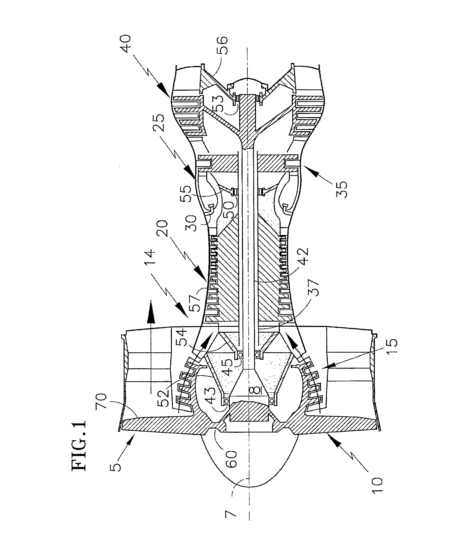
[0016]Referring to FIG. 1, a turbofan gas turbine engine 5 has a longitudinal axis 7 about which the rotors 8 of the engine rotate. A fan 10 disposed at the engine inlet draws air into the engine. A low pressure compressor 15 located immediately downstream of fan 10 compresses air exhausted from fan 10 and a high pressure compressor 20 located immediately downstream of low pressure compressor 15, further compresses air received therefrom and exhausts such air to combustors 25 disposed immediately downstream of high pressure compressor 20. Combustors 25 receive fuel through fuel injectors 30 and ignite the fuel / air mixture. The burning fuel-air mixture (working medium fluid) flows axially to a high pressure turbine 35 which extracts energy from the working medium fluid and in so doing, rotates hollow shaft 37, thereby driving the rotor of high pressure compressor 20. The working medium fluid exiting the high pressure turbine 35 then enters low pressure turbine 40, which extracts furt...


PUM


Abstract

A mounting arrangement for a gas turbine engine blade having a root employs a lightweight, simple and economical leaf spring spacer which biases the blade root in a radially outward direction to minimize unwanted movement of the root within a conforming slot in a blade hub under conditions such as windmilling when centrifugal force alone is inadequate to tightly seal the root within the slot.

Description

BACKGROUND OF THE INVENTION[0001]1. Technical Field[0002]This invention relates generally to gas turbine engines and particularly to a mounting arrangement for gas turbine engine blades such as fan blades.[0003]2. Background Information[0004]Turbofan gas turbine engines such as those which power aircraft employ a multiplicity of fan blades attached to a hub mounted on the forward (upstream) end of one of the engine shafts. Typically, such fan blades are provided with a radially outer airfoil shaped portion and a radially inner root portion typically having a dovetail shape. The dovetail shaped root portion is received within a slot which conforms thereto in the fan hub. For ease in attaching the fan blade to the hub by sliding the root portion into the slot and for removal of the blade from the hub by sliding the root portion of the blade out of the slot, the slot is usually slightly larger than the dovetail root portion. This difference in dimensions between the root portion of the...

Claims


Application Information

Patent Timeline
Patent Type & Authority Patents(United States)
IPC IPC(8): F01D5/02
CPCF01D5/3007Y02T50/672F01D5/323F05D2300/501Y02T50/60
Inventor WARD, ERIC J.RICHARDSON, BRIAN K.
Owner RTX CORP
Why Eureka
Try Eureka