
Turbocharger with magnetic bearing system that includes dampers

Inactive Publication Date: 2005-01-25
BORGWARNER INC
View PDF3 Cites 17 Cited by
  • Summary
  • Abstract
  • Description
  • Claims
  • Application Information

AI Technical Summary

Benefits of technology

The invention therefore has the object to configure the bearing of an exhaust gas turbocharger in such a way that, when permanent-magnetic radial bearings are used, sufficient damping of radial movements of the rotor is achieved.
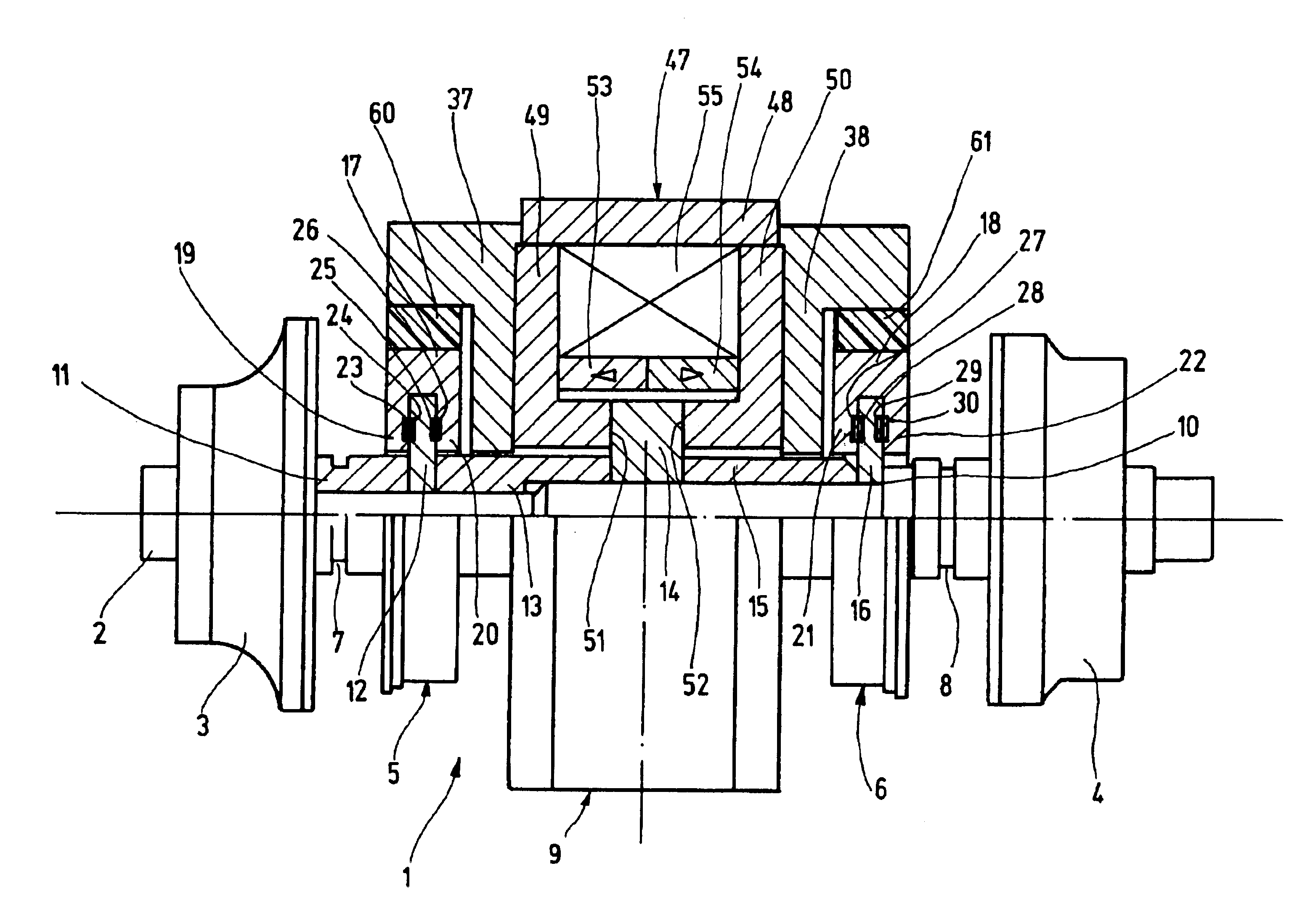
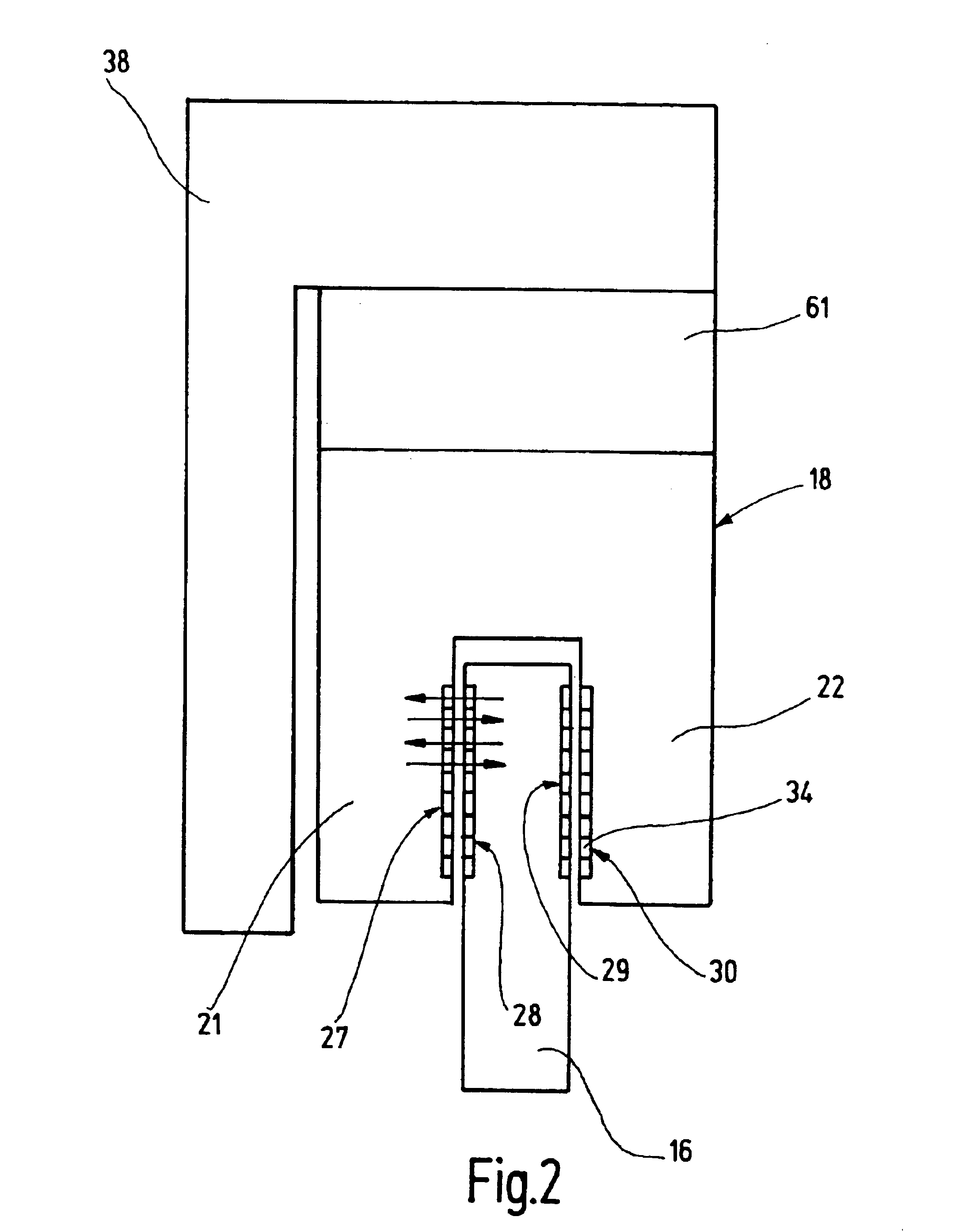
According to the invention, it is proposed that a resilient element for radially damping oscillation movements of the shaft be arranged between each stator and a part which is fixed to the housing. The resilient element is subjected to pressure by radial movements of the stator and in this way impedes the radial movements of the shaft and has a damping effect.
In one preferred embodiment of the invention, the resilient element is embodied as a cylindrical ring which is arranged coaxially with respect to the shaft. As a result, a uniform damping effect is achieved over the entire circumference. The oscillations or vibrations in the rotating parts which occur while the turbocharger is operating depend, inter alia, on their mass and mechanical rigidity. This requires a specific spring stiffness and damping constant of the resilient element, which can be made available by suitably selecting the material composition of the element. The resilient element preferably has a spring stiffness between 200 kN / m and 600 kN / m as well as a damping constant between 100 kg / s and 300 kg / s. These values can readily be achieved if the resilient element is composed of a plastic material, preferably of rubber material.

Problems solved by technology

The resilient element is subjected to pressure by radial movements of the stator and in this way impedes the radial movements of the shaft and has a damping effect.

Method used


Image

  • Turbocharger with magnetic bearing system that includes dampers
  • Turbocharger with magnetic bearing system that includes dampers
  • Turbocharger with magnetic bearing system that includes dampers

Examples


Embodiment Construction

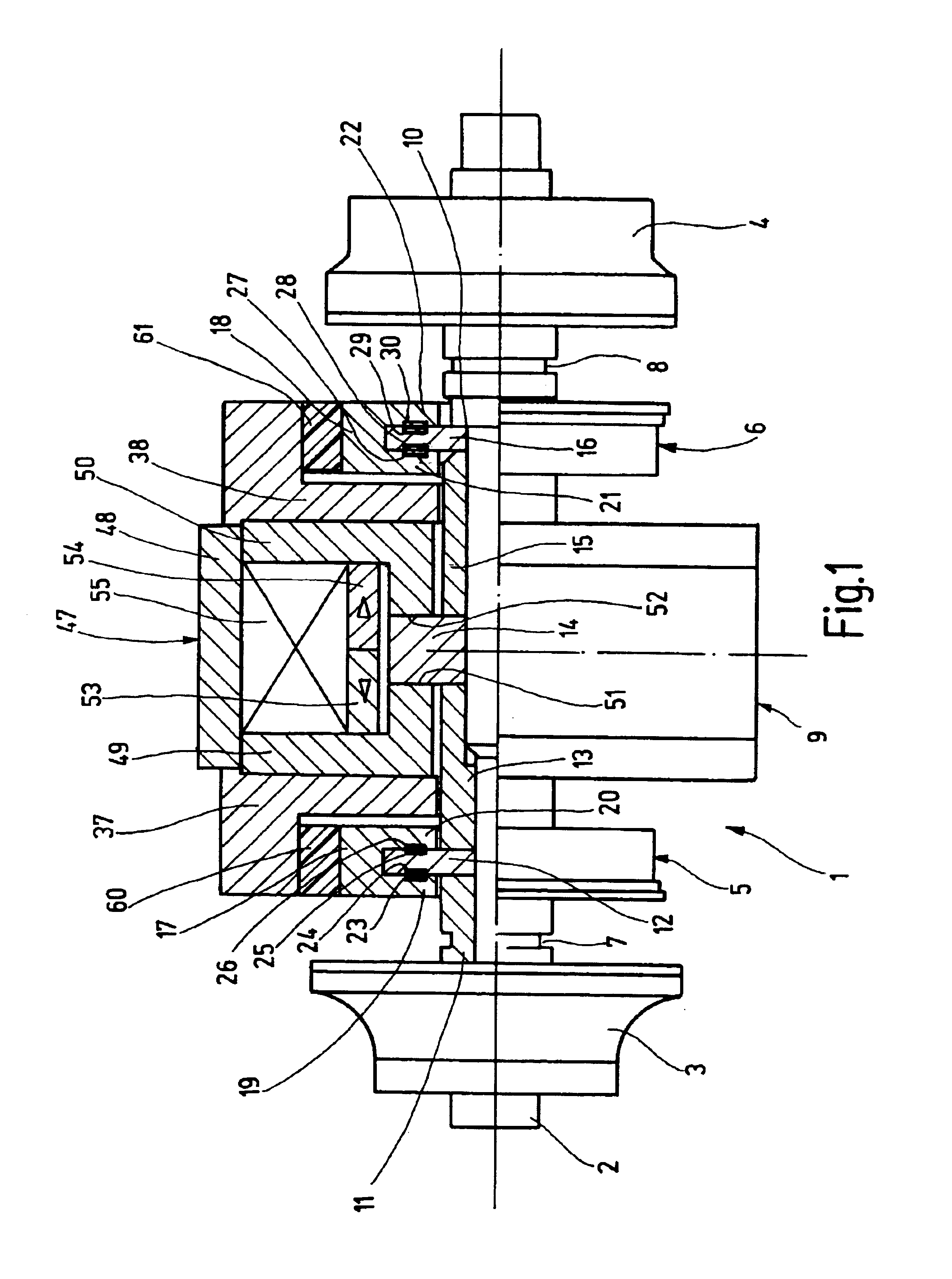
The exhaust gas turbocharger 1 which is illustrated in FIG. 1 has a shaft 2 at the left end of which a compressor wheel 3 is seated and at the right end of which a turbine wheel 4 is seated. The compressor wheel 3 is embodied as a radial compressor in a manner known per se.

Between the compressor wheel 3 and the turbine wheel 4 there are two radial bearings 5, 6. The radial bearings 5, 6 are adjacent to the compressor wheel 3 and the turbine wheel 4, respectively. Between them there are grooves 7, 8 which serve to hold sealing rings, said rings forming limiting bearings with a typical play of approximately ±0.15 mm. Between the radial bearings 5, 6 there is an axial bearing 9.

As is apparent from the upper part of FIG. 1, the shaft 2 is surrounded by a total of six rings which are clamped axially against a collar 10 on the shaft 2. A first shaft sleeve 11 with the groove 7 is followed by a bearing plate 12, a second shaft sleeve 13, a bearing plate 14, a third shaft sleeve 15 and a fu...


PUM


Abstract

The invention relates to an exhaust gas turbocharger (1) having a housing and having a shaft (2) which is arranged so as to be capable of rotating about its longitudinal axis in the housing and on which a turbine wheel (4) and a compressor wheel (3) are seated and which is guided in radial bearings (5, 6) and in at least one axial bearing (9), the radial bearings (5, 6) being embodied as passive, permanent-magnetic bearings which each have a bearing plate (12, 16) which is seated on the shaft (2) as a rotor, and at least one stator (19, 20, 21, 22) which is disposed axially opposite to said rotor. In order to achieve a radial oscillation damping of the shaft (2) in a simple manner, it is proposed according to the invention that a resilient element (60, 61) is disposed between the stator (19, 20, 21, 22) and a part (37, 38) which is fixed to the housing.

Description

BACKGROUND OF THE INVENTION1. Field of the InventionThe invention relates to an exhaust gas turbocharger having a housing and having a shaft which is arranged so as to be capable of rotating about its longitudinal axis in the housing and on which a turbine wheel and a compressor wheel are seated and which is guided in radial bearings and in at least one axial bearing, the radial bearings being embodied as passive, permanent-magnetic bearings each having a bearing plate which is seated, as a rotor, on the shaft, and at least one stator which is disposed axially opposite to said rotor.2. Description of the Related ArtExhaust gas turbochargers are used to improve the efficiency, and thus increase the performance, of internal combustion engines. They have a shaft which is provided at one end with a turbine wheel and at the other end with a compressor wheel. The turbine wheel has the exhaust gas stream of the internal combustion engine applied to it, essentially part of the thermal energ...

Claims


Application Information

Patent Timeline
IPC IPC(8): F01D25/16F16C39/00F16C39/06F02B39/00F16C27/06F16C32/04F16F15/08
CPCF01D25/164F16C39/063F16C2360/24F05D2220/40F05D2240/511
Inventor JAISLE, JENS-WOLF
Owner BORGWARNER INC
Learn More