Brake shoe and brake lining blocks with keyed connection

a technology of brake lining and drum brake, which is applied in the direction of friction lining, brake type, braking member, etc., can solve the problems of reducing braking performance, reducing braking performance, and cracking or breaking of the lining after securing to the shoe, so as to increase the resistance to shear forces

Inactive Publication Date: 2014-07-22
BERI MICHAEL
View PDF41 Cites 17 Cited by
  • Summary
  • Abstract
  • Description
  • Claims
  • Application Information

AI Technical Summary

Benefits of technology

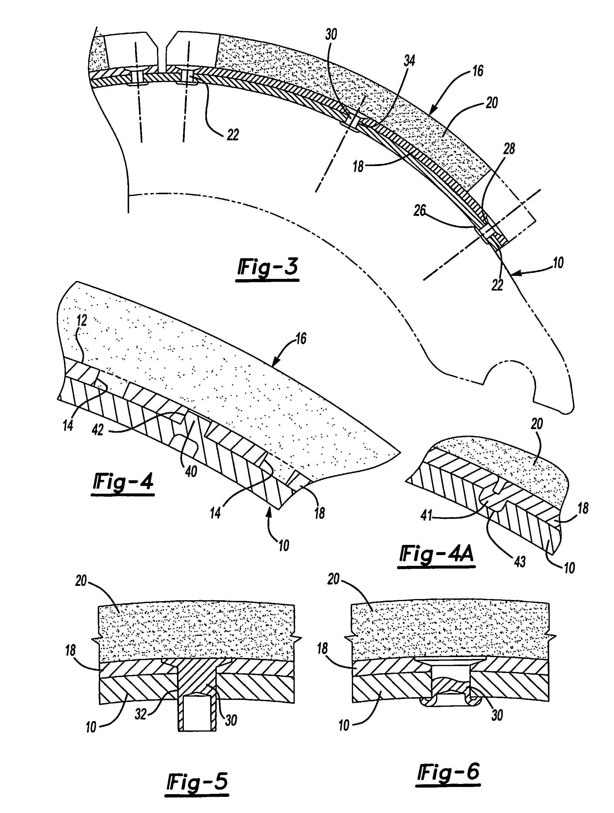
[0022]According to one aspect of the present invention, a brake shoe assembly is provided that includes a brake shoe and a brake plate. The brake shoe has an outer radial surface. The brake plate is secured to the outer radial surface of the brake shoe. A slot and an integrally formed key are provided between the brake shoe and brake plate. The slot and key prevent radial movement of the brake plate relative to the outer radial surface of the brake shoe. The slot and key also greatly increase resistance to shear forces when the brake is applied in comparison to conventional rivet secured brake linings. A plurality of fasteners, such as rivets or clinch bolts, may be provided for securing the brake plate to the brake shoe.
[0023]According to another aspect of the present invention, a vehicle brake drum shoe assembly is provided that includes a cylindrical brake shoe and at least one brake plate that is secured to the outer radial surface of the brake shoe. A pair of keys may be integrally formed by a punching operation in each of the cylindrical brake shoes to extend outwardly from the outer radial surface of the brake shoe. The brake plate is secured to the outer surface of the brake shoe and includes a pair of slots for receiving the keys of the brake shoe. The keys of the brake shoe are received in the slots in the brake plate and function to prevent radial movement of the brake plate relative to the outer radial surface of the brake shoe. Alternatively, the keys may be formed in a backing plate of the brake shoe and the slots may be formed in the brake shoe.
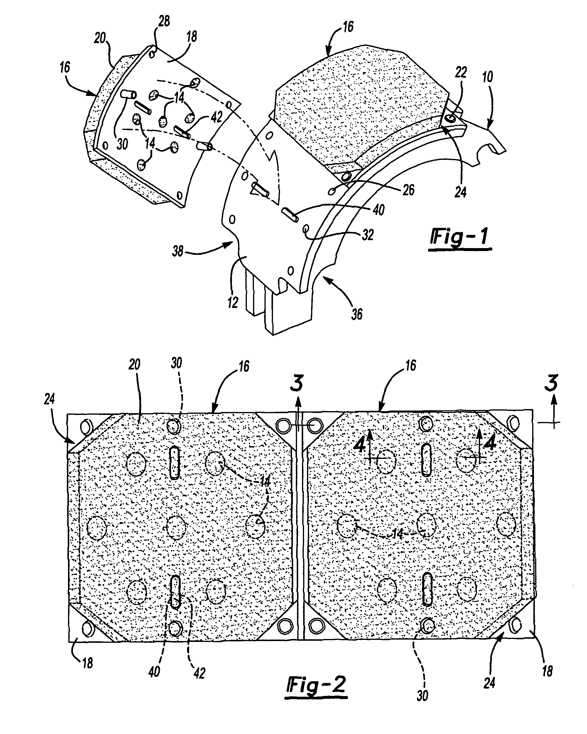
[0025]Other aspects of the invention relates to the concept of forming four recesses at the four corners of the brake plate to expose a corner portion of the brake plate. Fasteners are inserted through the four exposed corner portions to join the brake plate and brake shoe after the preassembled fasteners align the brake shoe key with the brake plate slot. The brake plate may then be secured to the brake shoe to thereby provide metal-to-metal contact and eliminating the need to fasten through the friction material. The brake plate slot is axially elongated to receive the elongated brake shoe keys. The backing plates span the friction lining surface and provide additional strength for the brake linings as they are attached to the brake shoe.
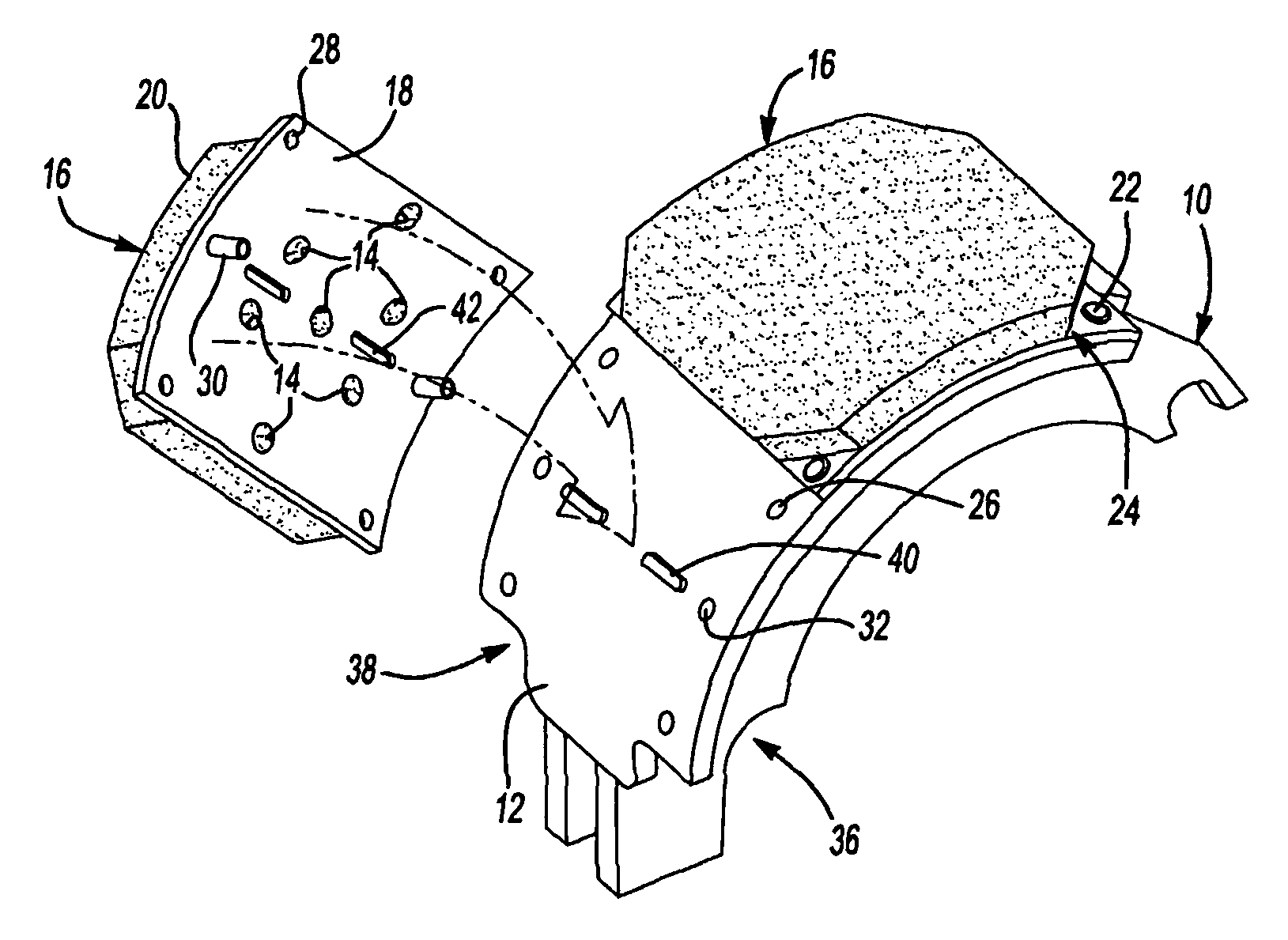
[0027]According to another aspect of the present invention, a method of manufacturing a brake assembly is provided. The method begins by providing a brake plate having a plurality of fastener apertures and an alignment slot. Four apertures may be provided at four corners of the brake plate with two intermediate apertures being provided at opposite sides of the brake plate. A set of preassembled fasteners are inserted into the two intermediate apertures of the brake plate. A frictional brake lining is then molded over the preassembled fasteners so that the frictional brake lining covers the preassembled fasteners. A brake shoe having a plurality of apertures that match the apertures in the brake plate also further includes a key that protrudes from the outer radial surface of the brake shoe. Each of the brake plate slots receives a brake shoe key when the brake plate is mated to the brake shoe. The preassembled fasteners are aligned with corresponding holes in the brake shoe to facilitate inserting the brake shoe key into the brake plate slot. Alternatively, the keys and slots could be on the brake plate and brake shoe, respectively. A set of fasteners is inserted in each of the fastener apertures in the corners of the brake plate. The fasteners extend through corresponding holes in both the brake plate and the brake shoe and are secured by a fastener tool in a fastening operation. The preassembled fasteners, if rivets, may be flared to secure the brake plate to the brake shoe. The brake shoe key when inserted in the brake plate slot limits, or prevents, movement of the brake plate relative to the outer radial surface of the brake shoe.
[0029]According to yet another aspect of the present invention, a brake shoe assembly is provided that includes a brake shoe and a brake plate. The brake shoe has an outer radial surface. The brake plate is secured to the outer radial surface of the brake shoe. At least one hole and an integrally formed cylindrical key are provided between the brake shoe and brake plate. The hole and cylindrical key prevent radial movement of the brake plate relative to the outer radial surface of the brake shoe. A plurality of fasteners are provided for securing the brake plate to the brake shoe. The fasteners may be rivets, clinch bolts or other fasteners.

Problems solved by technology

If the outer diameter of the brake shoe surface that is to be retrofit with new brake linings is not completely flat or within original design radius tolerances, the lining after securing to the shoe may crack or break off of the brake shoe.
This may create problems relating to braking performance and durability.
Worn or damaged brakes can cause reduced braking performance that may result in longer stopping distances.
If a brake lining becomes dislodged in whole or in part, the brake for a wheel can jam or lock-up and could result in a truck jack knifing.
Rivet holes in friction material interrupt the smooth surface of the friction material and reduce the available braking surface.
Reduction of the braking surface can increase temperature stress on the friction material.
Corners of the friction material can be damaged during assembly or in use and heat stress at the corners can lead to fractures.
If a brake plate or part of the friction lining material becomes detached from the brake shoe in an emergency, the brake assembly could lock-up or be otherwise seriously compromised.
If the counter bore is not drilled deep enough, the brake block may crack when riveted to the to the brake shoe by a riveter.
This condition can lead to cracking of the friction material or other problems.
If the rivet tool misses a rivet location and contacts the friction material, it may harm the friction material.
The friction material may be cracked, broken, or deformed if the rivet is misdirected, or improperly set-up for depth and rivet application force.
Any cracking, breakage or deformation could adversely impact braking performance of the lined brake shoe when installed on a vehicle.
Substantial labor costs are incurred to rivet brake blocks to a brake shoe.
Additional expenses may be incurred if it is necessary to scrap a cracked brake block.
Any reduction in surface area of the friction material may adversely affect stopping performance.
Holes for rivets in the surface of the friction material may result in unwanted noise especially if dirt or other foreign material is permitted to collect in the rivet access holes.
In the manufacture of brake blocks, problems may be encountered including blistering at the corners of the brake blocks.
The corners of brake blocks may be broken or damaged especially if the corners are formed with right angle corners.
If the brakes are frequently used in reverse or if the brakes are applied in an emergency stop while the vehicle is moving in reverse, the rivets may distort or stretch rivet holes in the friction material.
If the rivets holes become enlarged the friction material may become loose.
Any looseness of the rivets relative to the friction material may create unwanted noise or improper brake feel.
When brake shoes are rebuilt and reinstalled in a vehicle, the first brake application may result in only 40% to 50% of the surface of the friction material actually contacting the brake drum.

Method used


Image

  • Brake shoe and brake lining blocks with keyed connection
  • Brake shoe and brake lining blocks with keyed connection
  • Brake shoe and brake lining blocks with keyed connection

Examples


Embodiment Construction

)

[0048]Referring to FIG. 1, a brake shoe 10 having a cylindrical outer surface 12 is illustrated with one brake plate 16 assembled to the cylindrical outer surface 12 and a second brake plate 16 that is shown unattached to the brake shoe 10. Each of the brake plates 16 includes a backing plate 18 to which a layer of friction material 20 is bonded. A plurality of apertures 14 are provided in the backing plate 18 into which friction material 20 is integrally molded to mechanically attach the friction material 20 to the backing plate 18.

[0049]The brake plates 16 are attached, in part, by fasteners 22 that are secured to the backing plate 18 at open corners 24. While the illustrated embodiment shows rivets 22, other fasteners can be used instead of rivets and references to rivets should be construed to include other types of fasteners as well. The open corners 24 are areas where no friction material 20 is bonded to the backing plate 18. Alternatively, the layer of friction material 20 c...


PUM


Abstract

A brake shoe assembly comprising a brake shoe to which brake plates are assembled. The brake shoe and brake plates are connected by a key or tang in one to a key way or slot in the other. Preassembled fasteners are provided on the brake plates to facilitate alignment of the brake plates with the brake shoe so that the key is received in the slot. Fasteners may be provided in four open corner areas so that the brake plate may be secured to the brake shoe with metal-to-metal contact where the brake plate is secured to the brake shoe. A brake shoe having a cylindrical outer surface or an outer surface defined by a plurality of flats is provided.

Description

CROSS-REFERENCE TO RELATED APPLICATIONS[0001]This application is a continuation-in-part of U.S. application Ser. No. 10 / 684,877 filed Oct. 13, 2003 which is now issued as U.S. Pat. No. 6,983,831. This application also claims the benefit of provisional application 60 / 513,085 filed Oct. 21, 2004.BACKGROUND OF THE INVENTION[0002]1. Field of the Invention[0003]The present invention relates to drum brake shoes and brake lining blocks for vehicles such as trucks or buses.[0004]2. Background Art[0005]Vehicle brakes are generally either disk brakes or drum brakes. Drum brakes are generally preferred for buses and commercial trucks because drum brakes may provide a greater surface area of friction material. The braking surface of the friction material is generally riveted to a backing plate of a brake block. Generally, 12 to 16 rivets are required to attach a brake block to a brake shoe due to the substantial shear forces that must be withstood during braking between the brake blocks and the...

Claims


Application Information

Patent Timeline
Patent Type & Authority Patents(United States)
IPC IPC(8): F16D65/00F16D65/04B60TF16D65/08F16D69/04
CPCF16D65/08
Inventor BERI, MICHAEL
Owner BERI MICHAEL
Why Eureka
Try Eureka