Communication apparatus, communication system, control method, and storage medium
a technology of communication apparatus and control method, applied in the direction of transmission monitoring, modulation, electrical apparatus, etc., can solve the problem of consuming more power than is necessary
- Summary
- Abstract
- Description
- Claims
- Application Information
AI Technical Summary
Benefits of technology
Problems solved by technology
Method used
Image

Examples
first embodiment
General Directivity Angle Search
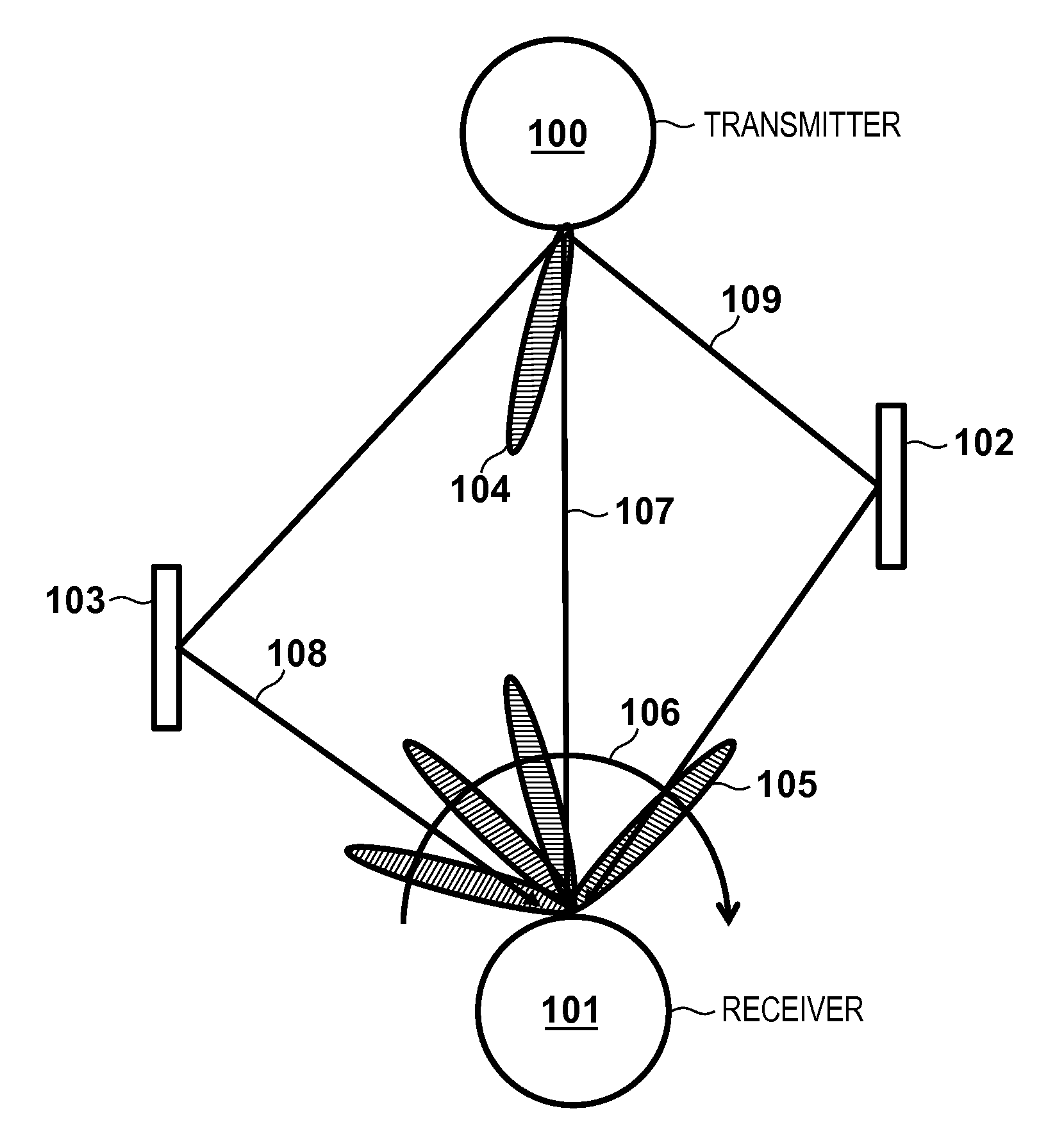
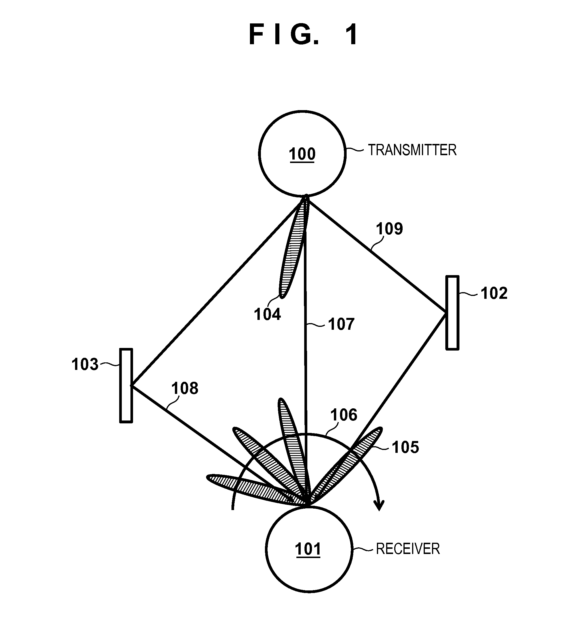
[0030]FIG. 1 schematically illustrates a general directivity angle search. A transmitter 100 transmits data signals using antennas that have directivity characteristics 104. Transmitted signals are received by a receiver 101 through a communication path 107 that is not affected by reflection or the like and communication paths 108 and 109 that involve reflection from reflectors 102 and 103. Here, radio waves that are received through a communication path that involves neither reflection nor diffraction are referred to as “direct waves”, and radio waves that are reflected and then received are referred to as “reflected waves”. Note that the receiver 101 receives signals using antennas that have directivity characteristics 105.
[0031]As mentioned above, in a wireless communication system that performs communication using variable antenna directivity characteristics, both communication apparatuses, namely the transmitter 100 and the receiver 101, need to ...
second embodiment
[0070]Next, a second embodiment will be described with reference to the drawings. The configurations of a wireless communication system, a transmitter 300, and a receiver 301 according to the present embodiment are similar to those described in the first embodiment, and thus a description thereof has been omitted. In the present embodiment, in order to further shorten the time required for the receiver 301 to perform reception operations, the time when a timing signal 701 similar to that of the first embodiment is switched from on to off when repeating the directivity angle search using the timing signal 701 is changed.
[0071]FIG. 11 shows a timing signal according to the present embodiment. In the present embodiment, for example, referring to FIG. 8A, when the arrival of radio waves is determined using the directivity characteristic 801 of the receiving antennas and the directivity characteristic 800 of the transmitting antennas, the reflected wave 310 is detected. It is assumed her...
third embodiment
[0072]Next, a third embodiment will be described with reference to the drawings. The configurations of a wireless communication system, a transmitter 300, and a receiver 301 according to the present embodiment are similar to those described in the first embodiment, and thus a description thereof has been omitted. In the present embodiment, as in the second embodiment, the time when the timing signal is switched from on to off is changed in order to further shorten the time required for the receiver 301 to perform reception operations.
[0073]FIG. 12A shows a system for executing a directivity angle search according to the present embodiment. As shown in FIG. 12A, the transmitter 300 of the present embodiment transmits a training sequence using a directivity characteristic 1200, and the receiver 301 receivers the training sequence using first a directivity characteristic 1201 and then a directivity characteristic 1202.
[0074]In the present embodiment, when using the directivity characte...
PUM
 Abstract
Description
Claims
Application Information
 - R&D
- Intellectual Property
- Life Sciences
- Materials
- Tech Scout
- Unparalleled Data Quality
- Higher Quality Content
- 60% Fewer Hallucinations
Browse by: Latest US Patents, China's latest patents, Technical Efficacy Thesaurus, Application Domain, Technology Topic, Popular Technical Reports.
© 2025 PatSnap. All rights reserved.Legal|Privacy policy|Modern Slavery Act Transparency Statement|Sitemap|About US| Contact US: help@patsnap.com