
Power supply system for vehicle

a power supply system and vehicle technology, applied in the direction of electric devices, battery/fuel cell control arrangement, transportation and packaging, etc., can solve the problems of high voltage circuit voltage rise, power line that connects the main power supply and the control device may be broken, and the re-rise of the voltage immediately after the discharge control is not discussed sufficiently, so as to reduce the power consumption of the control device and reduce the power consumption of the microcomputer. , the effect of reducing the electric power

Active Publication Date: 2020-06-18
HONDA MOTOR CO LTD
View PDF0 Cites 5 Cited by
  • Summary
  • Abstract
  • Description
  • Claims
  • Application Information

AI Technical Summary

Benefits of technology

The patent text describes a power supply system for vehicles that allows for monitoring and control of voltage. The system includes a sub-electric power supply device that connects to the main circuit and control device, which can provide power to the control device when the main circuit is unable to do so. The control device can perform discharge control by consuming power from the main circuit, thus quickly reducing the main circuit voltage. The system also includes a resolver that detects the rotational angle of the electric power generator and a drive circuit that controls the voltage converter and the voltage converter's driving circuit. By implementing these techniques, the power supply system can provide a longer period of monitoring and control of the main circuit voltage, even in situations where the main circuit is not under active discharge control.

Problems solved by technology

However, the event that the voltage of the high voltage circuit rises again during the period after execution of discharge control at the time of collision of the vehicle until the vehicle is stopped may occur immediately after the first discharge control is performed.
However, in the technique disclosed by Japanese Unexamined Patent Application Publication No. 2016-52140, re-rise of the voltage immediately after the discharge control is not discussed sufficiently.
When the vehicle is in collision, a power line that connects the main power supply and the control device may be broken or a failure may occur in the main power supply.
In that case, there is a possibility that sufficient electric power cannot be supplied to the control device continuously, the control device cannot monitor the main circuit voltage continuously over a sufficient monitoring period, and when rise of the main circuit voltage is detected, the discharge control cannot be performed again.
As described above, when the vehicle is in collision, electric power may not be supplied from the main power supply to the control device.
In that case, electric power is supplied from the sub-electric power supply device to the control device, but the electric power supplied from the sub-electric power supply device to the control device has a limit.

Method used


Image

  • Power supply system for vehicle
  • Power supply system for vehicle
  • Power supply system for vehicle

Examples


Embodiment Construction

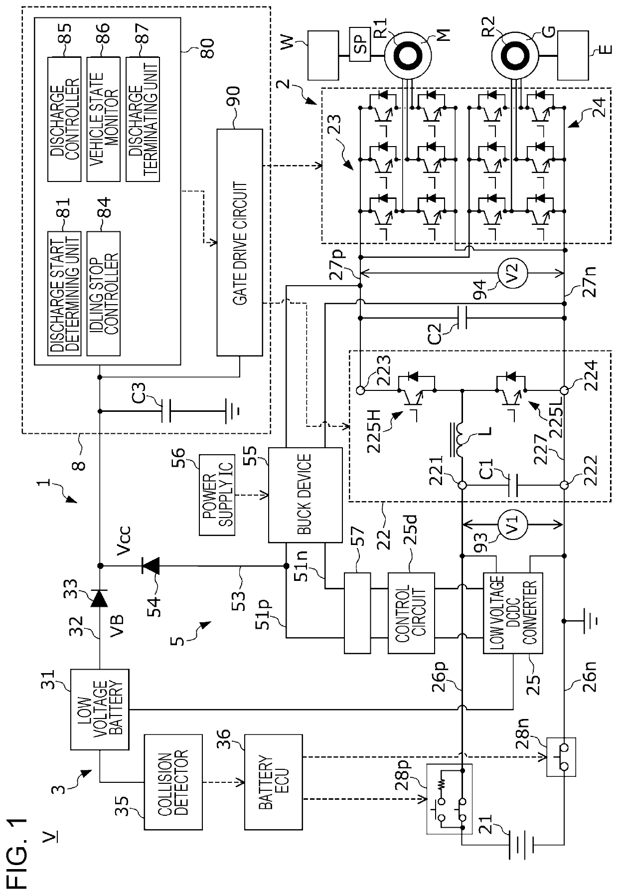
[0026]Hereinafter an embodiment of the present disclosure will be described with reference to the drawings. FIG. 1 is a diagram illustrating the configuration of an electric vehicle V (hereinafter simply referred to as a “vehicle”) equipped with a power supply system 1 according to the embodiment. It is to be noted that although so-called hybrid vehicle including an engine E, a drive motor M, and an electric power generator G will be described as an example in the embodiment, the present disclosure is not limited to this. The power supply system according to the present disclosure is applicable to not only a hybrid vehicle but also any vehicle provided that the vehicle, such as an electric automobile and a fuel cell automobile, which runs using the power stored in a battery.

[0027]The vehicle V includes the power supply system 1, the engine E, the drive motor M serving as an electric motor generator, an electric power generator G, drive wheels W, and a vehicle speed sensor SP. The dr...


PUM


Abstract

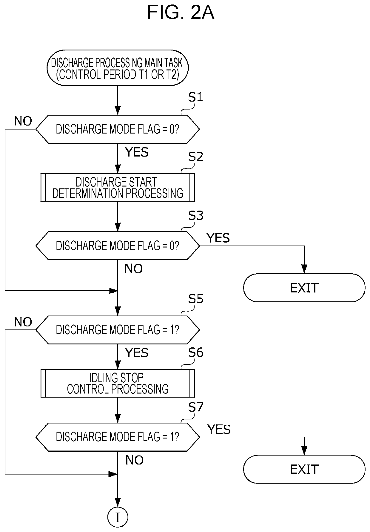
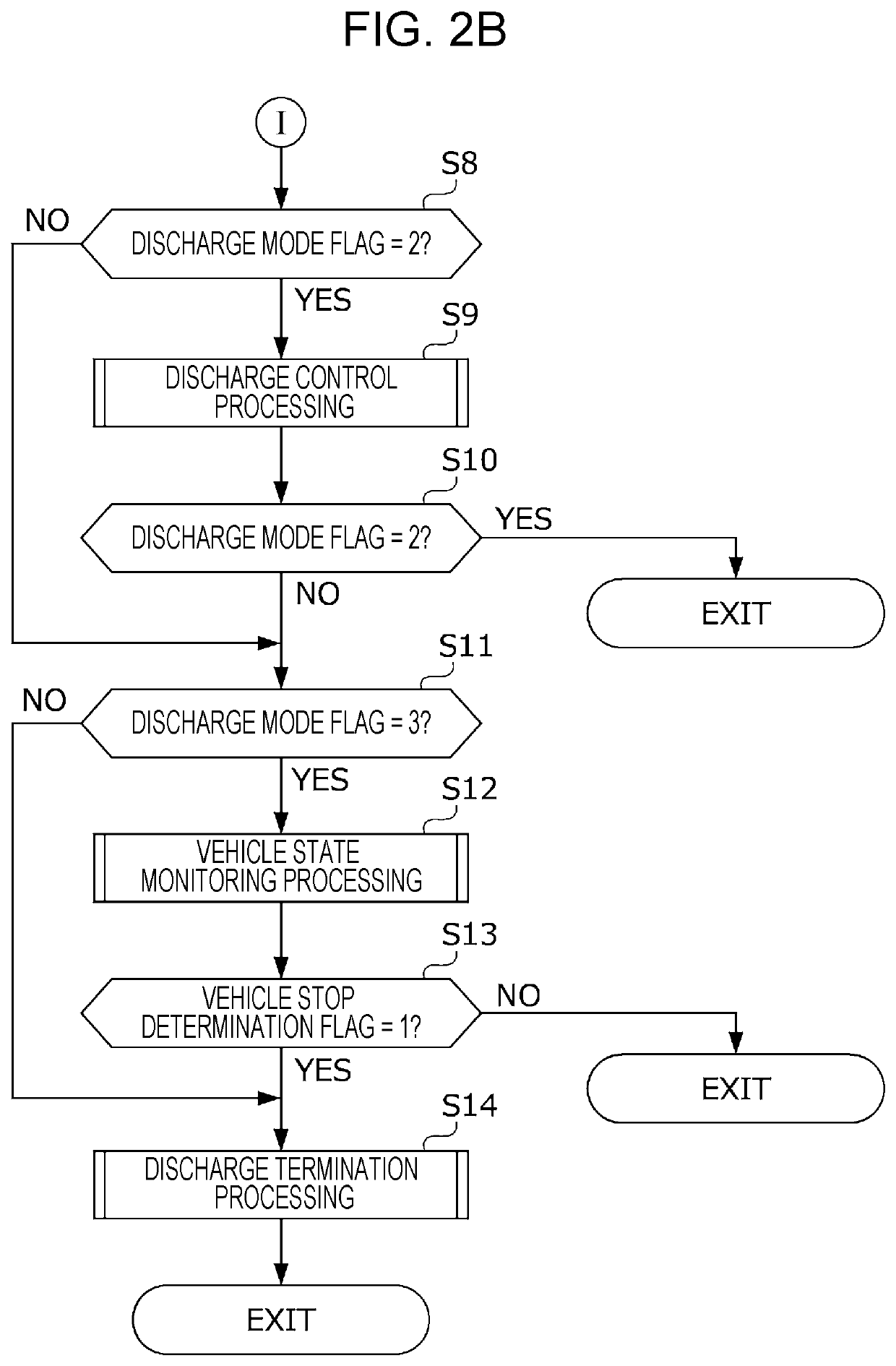
A power supply system includes a high voltage circuit; a system ECU that controls the high voltage circuit; and a backup power supply unit that supplies electric power in the high voltage circuit to the system ECU. The system ECU includes a discharge controller that performs discharge control to discharge the electric charges in a smoothing capacitor until a secondary-side voltage is reduced to a discharge termination determination voltage or lower; and a vehicle state monitor that determines whether a vehicle is in a stopped state, and determines whether the secondary-side voltage is lower than or equal to a re-rise determination voltage in a monitoring period from termination of the discharge control until the vehicle is determined to be in the stopped state. When the secondary-side voltage is determined to be higher than the re-rise determination voltage by the vehicle state monitor, the discharge controller performs the discharge control again.

Description

CROSS REFERENCES TO RELATED APPLICATIONS[0001]The present application claims priority under 35 U.S.C. § 119 to Japanese Patent Application No. 2018-234522, filed Dec. 14, 2018, entitled “Power Supply System for Vehicle.” The contents of this application are incorporated herein by reference in their entirety.BACKGROUND1. Field[0002]The present disclosure relates to a power supply system for a vehicle. More specifically, the present disclosure relates to a power supply system for a vehicle that, when a discharge start condition is met, performs discharge control to discharge charges in a main circuit which connects an electricity storage device and an electric motor generator.2. Description of the Related Art[0003]In an electric vehicle such as a hybrid automobile and an electric automobile, a power supply system is mounted, and the electric vehicle runs by driving a motor using the electric power supplied from the power supply system. The power supply system includes a high voltage b...

Claims


Application Information

Patent Timeline
Patent Type & Authority Applications(United States)
IPC IPC(8): B60L3/00
CPCB60L3/0046B60L2210/12B60L3/0061B60L3/0007B60L3/04B60L58/10B60L2210/00Y02T10/70
Inventor TAKAHASHI, MASAYA
Owner HONDA MOTOR CO LTD
Learn More