Power state diagnosis method and apparatus

a power state and diagnosis method technology, applied in underwater vessels, special data processing applications, non-deflectable wheel steering, etc., can solve the problems of battery degradation (voltage drop), large influence of battery degradation, and inability to obtain the desired assist force, etc., to achieve excessively increase the responsibility and fast control period

Inactive Publication Date: 2013-07-25
NSK LTD
View PDF0 Cites 7 Cited by
  • Summary
  • Abstract
  • Description
  • Claims
  • Application Information

AI Technical Summary

Benefits of technology

[0017]The present invention detects that a driver does not steer at a time that an ignition key is switched from “OFF” to “ON” or at a time that the ignition key is switched from “ON” to “OFF”, stores a value obtained by adding an offset to a motor angle that is read at the time as a pseudo-motor-angle, and drives the motor based on the pseudo-motor-angle that is stored during the diagnosis so that it is possible to diagnose the battery state in a state that the motor is fixated (in the present invention, “fixation” means a state that the motor does not rotate). Therefore, the present invention does not give an uncomfortable feeling to the driver.
[0018]Further, even in the middle of the diagnosis, in the case that the steering torque or the motor angle varies due to the operation of the driver, since the present invention interrupts the diagnosis and returns to the ordinary control, so the present invention does not give an uncomfortable feeling to the driver.
[0019]Moreover, by using the fixed pseudo-motor-angle, the present invention does not need to make the control period fast, use an expensive control unit and excessively increase the responsibility.

Problems solved by technology

Usually, since an electricity consumption of such an electric power steering apparatus is considerably high, there is a possibility that the influence of battery degradation is large and it is impossible to obtain a desired assist force when the voltage drops.
However, failures such as battery degradation (voltage drop) due to various causes, occur.

Method used


Image

  • Power state diagnosis method and apparatus
  • Power state diagnosis method and apparatus
  • Power state diagnosis method and apparatus

Examples


first embodiment

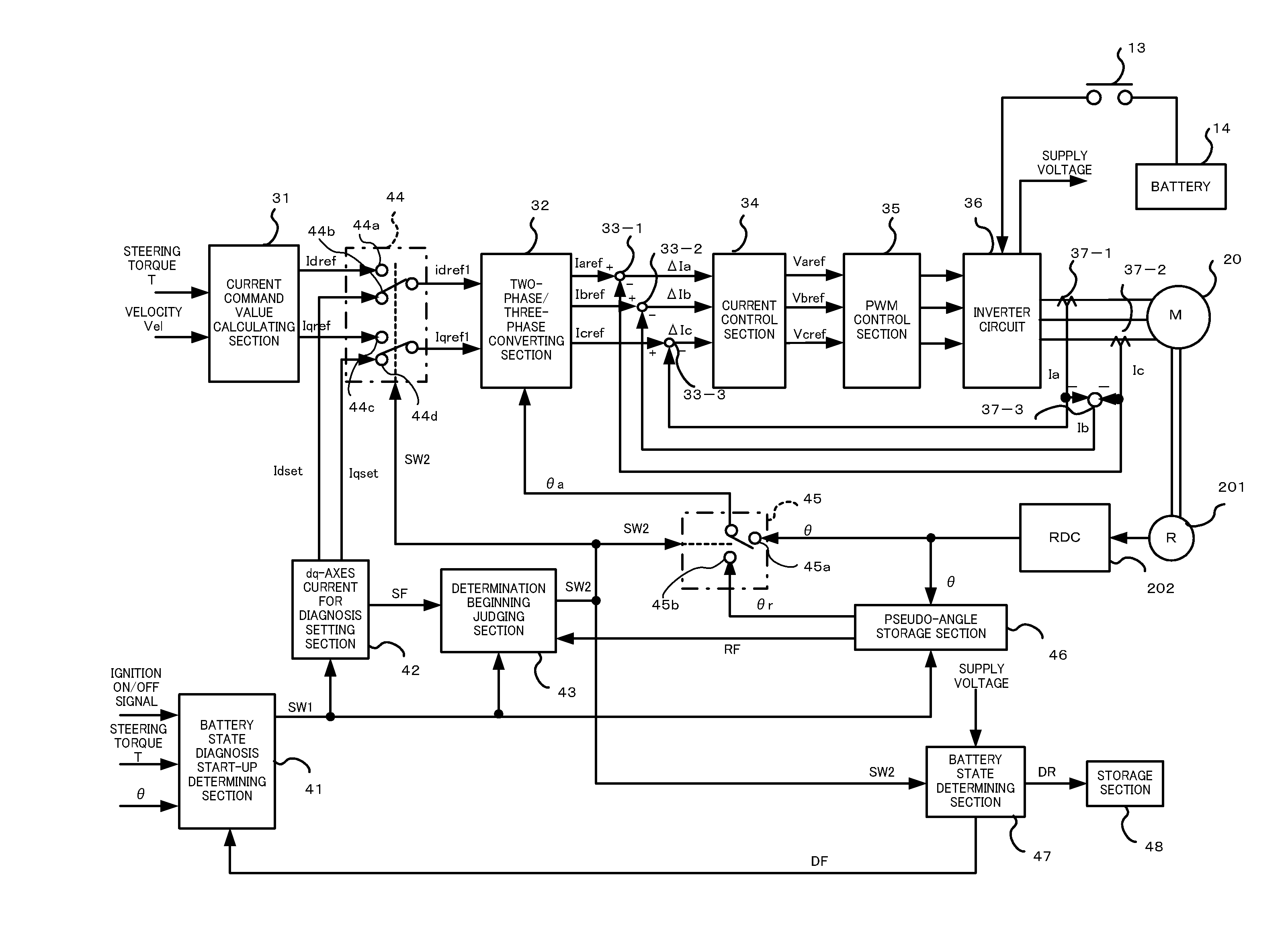
[0033]FIG. 3 is a block diagram showing a configuration of a battery state diagnosis apparatus according to the first embodiment of the present invention, the portion of the electric power steering apparatus is shown as corresponding to FIG. 2, with respect to identical configurations, identical reference numerals are given without adding explanations.

[0034]In order to diagnose the state of the battery 14, a battery state diagnosis start-up determining section 41, a dq-axes current for diagnosis setting section 42, a determination beginning judging section 43, a switching section 44, a switching section 45, a pseudo-angle storage section 46, a battery state determining section 47 and a storage section 48 are provided.

[0035]The battery state diagnosis start-up determining section 41 inputs an ON / OFF signal of the power relay that operates in accordance with the ignition key 11, the steering torque T detected by the torque sensor 10 and the motor angle θ that is detected by the resolv...

second embodiment

[0052]FIG. 6 shows a configuration of a battery state diagnosis apparatus according to the second embodiment of the present invention as corresponding to FIG. 3, with respect to identical configurations, identical reference numerals are given without adding explanations.

[0053]In this embodiment, in order to diagnose the state of the battery 14, as the first embodiment, a battery state diagnosis start-up determining section 41, a dq-axes current for diagnosis setting section 42, a determination beginning judging section 43, a switching section 44, a switching section 45, a pseudo-angle storage section 46, a battery state determining section 47 and a storage section 48 are provided. Moreover, a calculating section 38 and a switching section 49 are further provided.

[0054]In the first embodiment, even during the diagnosis, by means of the current control section 34 that is a feedback control, the subtracting sections 33-1, 33-2 and 33-3, making the deviation between the current command ...

third embodiment

[0058]FIG. 7 is a block diagram that is obtained by changing the battery 14 of the block diagram of FIG. 3 that shows one configuration of the battery state diagnosis apparatus according to the first embodiment, parts differing from the first embodiment will be described. A battery 14 of the third embodiment shows an example of battery configurations equipped with electrical vehicles. The battery 14 has a main battery 14-1 and an auxiliary battery 14-3, the voltage of the main battery 14-1 is monitored by a voltage monitoring section 14-4. The battery 14 has a power-supply configuration that at the normal time, the power supply is supplied from the main battery 14-1 through a power-supply switching section 14-2, and at the time that the voltage monitoring section 14-4 detects abnormalities or failures in the voltage of the main battery 14-1, the power supply is supplied from the auxiliary battery 14-3 by switching the power-supply switching section 14-2. That is, a power-supply conf...


PUM


Abstract

[Problem]
An object of the present invention is to provide a power state diagnosis method and a power state diagnosis apparatus that do not need to make a control period fast and also do not need to excessively increase a responsibility, and do not give an uncomfortable feeling to a driver.
[Means for Solving the Problem]
The present invention is a power state diagnosis method that diagnoses a power state of a vehicle which comprises an electrical control system supplied from a power supply and a motor controlled by a vector control method, comprising: starting a diagnosis of said power state at a time that an ignition key is switched from “OFF” to “ON” or at a time that said ignition key is switched from “ON” to “OFF”, storing a value obtained by adding an offset to an angle of said motor that is read at a start of said diagnosis as a pseudo-motor-angle, performing said vector control based on said pseudo-motor-angle during said diagnosis, and diagnosing said power state based on a voltage that is supplied to said motor.

Description

TECHNICAL FIELD[0001]The present invention relates to a power state diagnosis method and a power state diagnosis apparatus that diagnose a state of a power supply (a battery) that is supplied to plural electrical control systems provided at a vehicle, and in particular to a power state diagnosis method and a power state diagnosis apparatus that diagnose the state of the power supply that is supplied to an electric power steering apparatus which provides a steering system with an assist force by a motor.BACKGROUND ART[0002]Heretofore, it is well known that an electric power steering apparatus is one of electrical control systems that are supplied from a battery as a power supply. The electric power steering apparatus drives a motor based on a steering torque inputted by a driver and so on to provide a steering system with an assist force. Usually, since an electricity consumption of such an electric power steering apparatus is considerably high, there is a possibility that the influe...

Claims


Application Information

Patent Timeline
Patent Type & Authority Applications(United States)
IPC IPC(8): H02P31/00B60R16/04B62D5/04B62D6/00B62D119/00
CPCB62D5/0481H02P31/00G01R31/3627G01R31/3679B60R16/0232G01R31/385G01R31/392
Inventor SAKAGUCHI, TORU
Owner NSK LTD
Why Eureka
Try Eureka