Coupling arrangement for the front of a tracked vehicle

a track vehicle and front-mounted technology, applied in the direction of railway coupling accessories, draw-gear, buffers, etc., can solve the problems of potential damage, interfering with adjacent freight car bodies, and insufficient absorbing devices to absorb the overall accumulated energy, so as to prevent the effect of overriding motion

Active Publication Date: 2013-05-23
VOITH PATENT GMBH
View PDF7 Cites 14 Cited by
  • Summary
  • Abstract
  • Description
  • Claims
  • Application Information

AI Technical Summary

Benefits of technology

[0039]The advantages resulting from the use of a deformation tube of the type mentioned above as energy consuming element of the energy consuming device allocated to the crossbeam have already been described in connection with the energy consuming element of the energy consuming device allocated to the central buffer coupling. In particular, it allows the realization of a maximum energy consumption in connection with a foreseeable course of events and a small installation space.
[0040]For the particularly effective prevention of an overriding motion of two adjacent freight car bodies in case of a crash, it is advantageous if the crossbeam and / or the two longitudinal beams of the supporting structure comprise an override protector each on the corresponding sides facing the gladhand. These can in particular be horizontal braces which bring about the wedging of the adjacent freight car bodies.

Problems solved by technology

In contrast, if the operational load of the absorbing device is exceeded, such as if the vehicle hits an obstacle or if the vehicle is abruptly slowed down, there is a risk that the interface between the adjacent freight car bodies, in particular the absorbing device and the possibly provided link or coupling joint between the individual freight car bodies, may potentially get destroyed or damaged.
In any case, the absorbing device is inadequate to absorb the overall accumulated energy.
As a result, the absorbing device is then no longer incorporated in the energy consuming concept of the entire vehicle.
On the one hand, the disadvantage of said solution is that a relatively large space is required in the undercarriage of the freight car body for the reverse motion of the bearing bracket together with the deformation tube, because the deformation tube is pushed through the nozzle plate into an additionally required space behind the coupling arrangement when the deformation tube is deformed, i.e., when the energy consuming device responds.
For coupling arrangements in which said additional space is not available, for instance because of the immediate vicinity of a bogie, it will not be possible to use the solution for the energy consuming device proposed in said prior art.
However, the solution disclosed in the printed document DE 43 02 444 A1 is in particular associated with the risk that the deformation tube, for example in the cone-shaped bore hole formed in the nozzle plate, tends to “seize up” or become wedged when the energy consuming device responds—especially in connection with a vertical or inclined load of the deformation tube, such that the function of a destructive energy consumption is no longer given.
More broadly speaking, the known energy consuming devices, such as ones described above, are associated with the basic risk that components which shift relative to the undercarriage of the vehicle in the direction of the vehicle in case of a crash jam during said axial displacement, whereby the achievable energy consumption is indefinite and in particular no previously definable course of events is given in connection with the energy consumption.
In detail, the risk associated with the solution described in DE 43 02 444 A1 is that the deformation tube itself, which is axially displaced toward the vehicle or freight car body together with part of the bearing bracket in this solution, becomes wedged or jammed or seizes up in the opening provided in the nozzle plate in case of a crash.

Method used


Image

  • Coupling arrangement for the front of a tracked vehicle
  • Coupling arrangement for the front of a tracked vehicle
  • Coupling arrangement for the front of a tracked vehicle

Examples


Embodiment Construction

[0060]Various embodiments now will be described more fully hereinafter with reference to the accompanying drawings, in which some, but not all embodiments of the inventions are shown. Indeed, these inventions may be embodied in many different forms and should not be construed as limited to the embodiments set forth herein; rather, these embodiments are provided so that this disclosure will satisfy applicable legal requirements. Like numbers refer to like elements throughout.

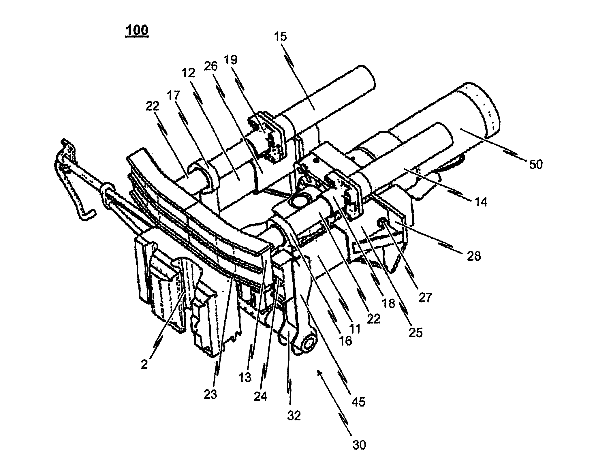
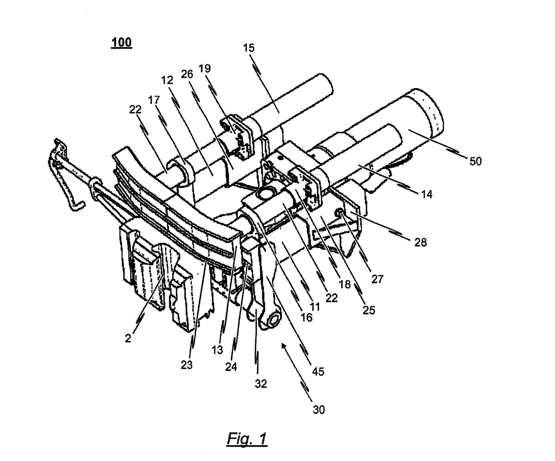
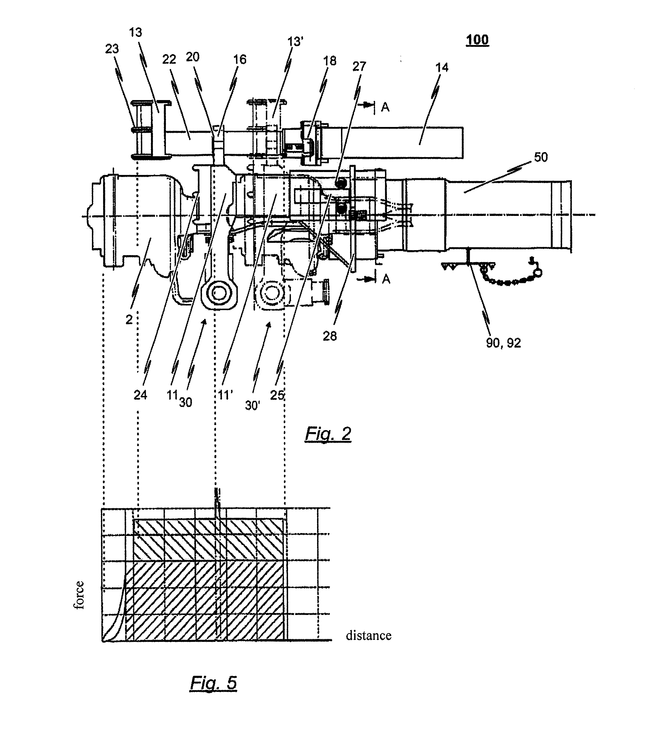
[0061]Below is a description of the design and functionality of an exemplary embodiment of the coupling arrangement 100 according to the invention, with reference to the illustrations in FIGS. 1 to 5.

[0062]As is best visible by the representation in FIG. 3, the purely exemplary illustration of the coupling arrangement 100 comprises a central buffer coupling 1 having a gladhand 2 and a coupling shaft 3 supporting the gladhand 2. The central buffer coupling 1 is an automated or semi-automated central buffer couplin...


PUM


Abstract

A coupling arrangement for the front of a tracked vehicle is disclosed, comprising a central buffer coupling having a gladhand, a coupling shaft supporting the gladhand and a bearing, via which the coupling shaft can be joined with the undercarriage of the vehicle pivotable in a horizontal and/or vertical direction. An energy consuming device allocated to the central buffer coupling having at least one energy consuming element with a destructive design is provided. To ensure maximum energy consumption in a crash with a course of events definable in advance, the coupling arrangement additionally comprises a supporting structure with two longitudinal beams arranged on the sides of the central buffer coupling and a crossbeam joined with the two longitudinal beams, said crossbeam beam being arranged above the central buffer coupling such that a vertical deflection of the coupling shaft relative to the undercarriage of the vehicle is limited by the crossbeam.

Description

CROSS-REFERENCE TO RELATED APPLICATIONS[0001]This application claims priority to European Patent Application Serial No. EP 11 189 905.0, filed Nov. 21, 2011, the contents of which is hereby incorporated by reference in its entirety.BACKGROUND OF THE INVENTION[0002]1. Related Field[0003]The present invention relates to a coupling arrangement according to the preamble of the independent patent claim 1.[0004]Accordingly, the invention in particular relates to a coupling arrangement for the front of a tracked vehicle, in particular a rail vehicle, wherein the coupling arrangement comprises a central buffer coupling having a gladhand, a coupling shaft supporting the gladhand and a bearing via which the coupling shaft can be joined with the undercarriage of the vehicle pivotable in horizontal and / or vertical direction, and wherein the coupling arrangement furthermore comprises an energy consuming device allocated to the central buffer coupling having at least one energy consuming element ...

Claims


Application Information

Patent Timeline
Patent Type & Authority Applications(United States)
IPC IPC(8): B61G7/00
CPCB61G7/00B61G3/16B61G11/16
Inventor EWERDING, THOMAS
Owner VOITH PATENT GMBH
Why Eureka
Try Eureka