Single- or multi-phase dry-type transformer having at least two coils

a dry-type transformer, single-phase technology, applied in the direction of transformer/inductance details, basic electric elements, coils, etc., can solve the problem of less compact transformer design

Active Publication Date: 2013-05-23
HITACHI ENERGY SWITZERLAND AG
View PDF9 Cites 2 Cited by
  • Summary
  • Abstract
  • Description
  • Claims
  • Application Information

AI Technical Summary

Problems solved by technology

This results overall in a less c

Method used


Image

  • Single- or multi-phase dry-type transformer having at least two coils
  • Single- or multi-phase dry-type transformer having at least two coils
  • Single- or multi-phase dry-type transformer having at least two coils

Examples


Embodiment Construction

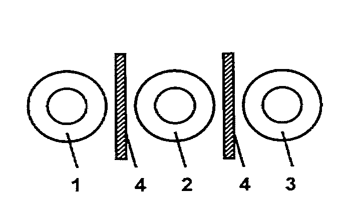
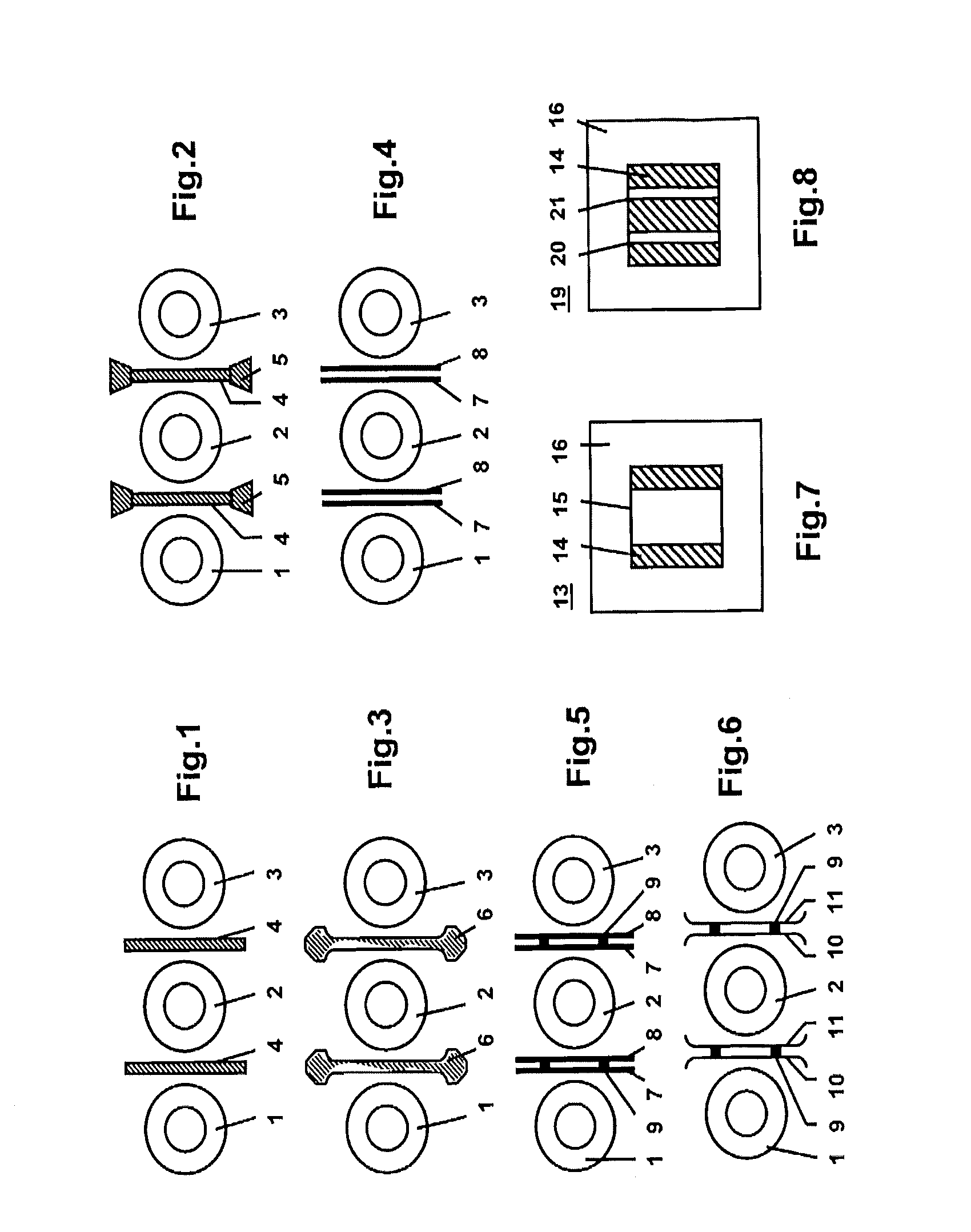
[0009]The present disclosure provides a single-phase or polyphase dry-type transformer with at least two coils which enables a compact design even at high voltages.

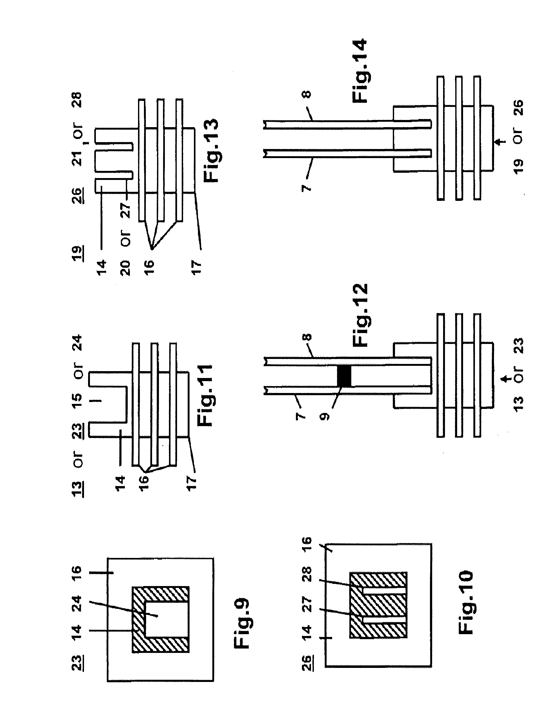
[0010]An exemplary embodiment according to the present disclosure provides a single-phase or polyphase dry-type transformer having at least two coils, wherein an interphase barrier made of (e.g., including in whole or in part) an electrically insulating material is arranged in the interspace between the individual coils.

[0011]Two coils can also be used for a single-phase transformer, in which one coil is arranged on each limb of a core with two limbs.

[0012]Due to the arrangement of the interphase barriers in the interspace between the individual coils, the required distances between the coils can be significantly reduced. A compact design of the dry-type transformer is thus achieved. In this case, both an individual barrier and a plurality of barriers arranged next to one another can be used per interspace. Such barriers ...


PUM


Abstract

A single- or multi-phase dry-type transformer includes at least two coils. A barrier between phases made of an electrically insulating material is arranged in the intermediate space between the individual coils.

Description

RELATED APPLICATION(S)[0001]This application claims priority as a continuation application under 35 U.S.C. §120 to PCT / EP2011 / 003160, which was filed as an International Application on Jun. 28, 2011 designating the U.S., and which claims priority to European Application 10007133.1 filed in Europe on Jul. 10, 2010. The entire contents of these applications are hereby incorporated by reference in their entireties.FIELD[0002]The present disclosure relates to a single-phase or polyphase dry-type transformer with at least two coils.BACKGROUND INFORMATION[0003]In the case of three-phase transformers, the three coils are generally arranged next to one another at an electrically safe distance. For instance, at high voltages, the distances between the coils associated with the three phases are relatively large in order to withstand the voltage loads during the surge voltage withstand testing. This results overall in a less compact design of the transformer.SUMMARY[0004]An exemplary embodimen...

Claims


Application Information

Patent Timeline
IPC IPC(8): H01F5/06
CPCH01F27/324H01F5/06H01F30/12H01F27/32
Inventor WEBER, BENJAMINPATEL, BHAVESHESENLIK, BURAKCORNELIUS, FRANKBOCKHOLT, MARCOSTEPPER, JENSMURILLO, RAFAELROY, CARLOS
Owner HITACHI ENERGY SWITZERLAND AG
Why Eureka
Try Eureka