Compact optical multiplexer/demultiplexer

a multi-multi-plexer and compact technology, applied in multiplex communication, instruments, optical elements, etc., can solve the problems of increasing the insertion loss of the filter, the center wavelength of the passband of the filter cannot be easily tuned, and the critical status of the coupler

Inactive Publication Date: 2005-09-06
JDS UNIPHASE CORP
View PDF7 Cites 9 Cited by
  • Summary
  • Abstract
  • Description
  • Claims
  • Application Information

AI Technical Summary

Benefits of technology

[0012]a first prism for redirecting the other wavelength channels of the WDM signal traveling between the second path and the third path, whereby the position of the second input / output port is independent of the reflection angle and the required distance between the first drop port and the second input / output port is reduced.
[0020]whereby the position of the second drop port is independent of the angle between the second and third paths, and the required distance between the first drop port and the second drop port is reduced.

Problems solved by technology

There are certain drawbacks to these conventional couplers, such as a certain amount of cross talk between the fibers 11 and 12 due to their close proximity.
However, due to the fact that the position of filter 41 is fixed, the center wavelength of the passband of the filter cannot easily be tuned.
As a result, selecting the appropriate filter for the desired passband before manufacturing the coupler becomes critical.
However, as is well known in the art, the bandwidth of the passband decreases as the angle of incidence increases, resulting in an increase in the insertion loss of the filter.
Furthermore, polarization dependent loss (PDL), i.e. the difference in the transmission of the S and P components of the signal, greatly increases with an increase in the angle of incidence.
However, this raises another problem related to the physical restraints of positioning two ports, each with their own lens and ferrule, beside each other.

Method used


Image

  • Compact optical multiplexer/demultiplexer
  • Compact optical multiplexer/demultiplexer
  • Compact optical multiplexer/demultiplexer

Examples


Embodiment Construction

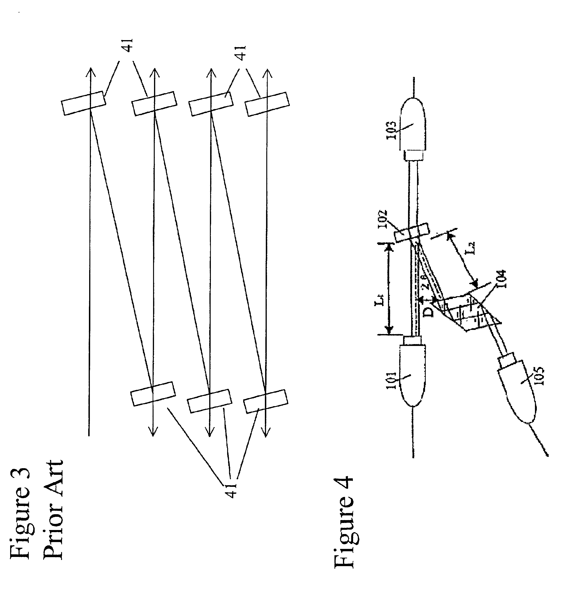
[0037]In contrast to FIG. 2, the WDM filter arrangement according to an embodiment of the present invention is illustrated in FIG. 4 and includes an input / output port 101, an optical filter 102, an add / drop port 103, a prism 104, and an output / input port 105. The ports 101, 103 and 105 include a single bore ferrule encasing an end of an optical fiber, which is optically coupled to a lens. The lens is typically a ¼ pitch graded index (GRIN) lens, such as those available under the trademark SELFOC® from NSG Co. Ltd. of Osaka, Japan.

[0038]The addition of the prism 104 enables the beam to be reflected at a relatively small angle of reflection, e.g. θi=θr=1.8°, without being a factor in the positioning of the output / input port 105. In the illustrated embodiment, the opposite faces of the prism 104 are parallel, which ensures that the beam exits the prism 104 along a path parallel to the path along which the beam entered the prism 104. The opposite faces of the prism 104 can be arranged a...


PUM


Abstract

The invention relates to wavelength division multiplexing (WDM) and demultiplexing of optical signals using optical filters in free space. To minimize dispersion, the present invention uses relatively small angles of incidence. To avoid the need for a large package, the present invention utilizes reflective prisms to steer the reflected beams to provide a lateral shift in the beam path that ensures that the necessary space is provided between the input / output ports. Devices including a single adjustable filter are disclosed, along with devices having a plurality of filters.

Description

TECHNICAL FIELD[0001]The present application relates to a wavelength division multiplexer / demultiplexer, and in particular to a compact wavelength division multiplexer / demultiplexer utilizing optical filters in free space.BACKGROUND OF THE INVENTION[0002]Conventional wavelength division multiplexing (WDM) couplers, such as the one disclosed in FIG. 1, include a double bore ferrule 21 encasing the ends of optical fibers 11 and 12, which are optically coupled to a lens 31. The lens 31 collimates a beam of light from the fiber 11 onto an optical filter 41, which passes light centered around a single wavelength. This wavelength corresponds to one or more channels. The remainder of the light is reflected back through the lens 31 and out the fiber 12. The light that is passed through the filter 41 is focused by a lens 32 onto a fiber 13, which is encased in a ferrule 22. Alternatively, when used as a multiplexer, light from the fiber 12 is reflected by the filter 41 and combined with ligh...

Claims


Application Information

Patent Timeline
Patent Type & Authority Patents(United States)
IPC IPC(8): G02B6/34H04J14/02
CPCG02B6/29367G02B6/2938G02B6/29395H04J14/0206H04J14/0213H04J14/0209H04J14/0219
Inventor WU, LIGUO, ZHANHUALING, JIWUZENG, HEPINGRUAN, ZHIZHANMA, JIAYONG
Owner JDS UNIPHASE CORP
Why Eureka
Try Eureka