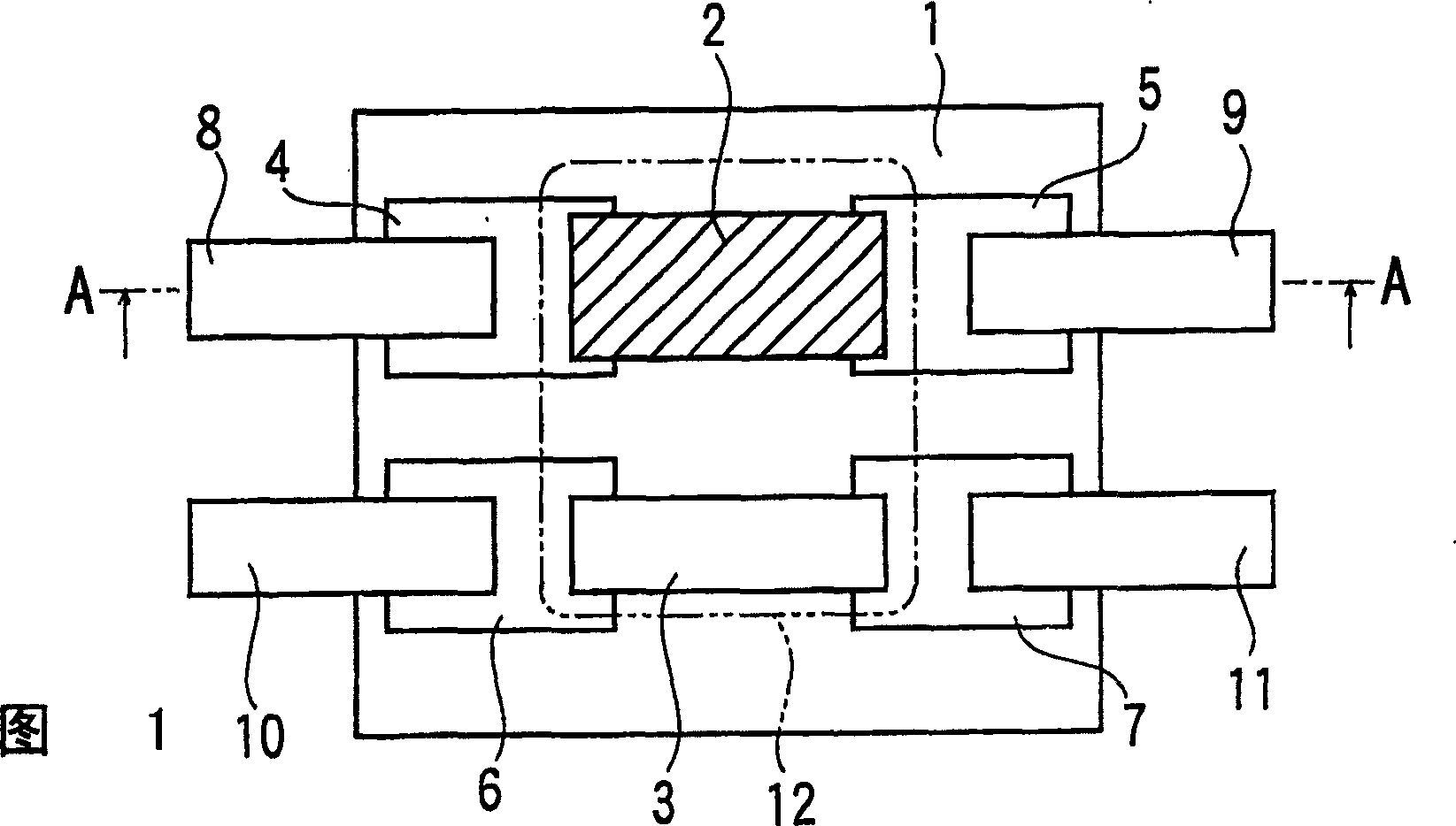
Protective device

A technology for protecting components and substrates, applied in electrical components, emergency protection devices, circuits, etc., can solve problems such as thinning of difficult-to-protect components, discrete thickness of protective components, and inability to guarantee the thickness of protective components, so as to achieve the effect of ensuring dimensional stability

Inactive Publication Date: 2006-03-15
DEXERIALS CORP
View PDF4 Cites 13 Cited by
  • Summary
  • Abstract
  • Description
  • Claims
  • Application Information

AI Technical Summary

Problems solved by technology

[0007] However, in the case of the method of mounting the insulating cover on the flux and sealing it by filling the surrounding with resin as in this prior art, it is difficult to control the thickness of the resin between the base substrate and the insulating cover, and there is a protective element The thickness of the whole produces a discrete bad case
[0008] In addition, in the method described in this prior art, the distance between the base substrate and the insulating cover depends on the amount of flux and the push-in pressure of the insulating cover, etc., due to uneven application of the flux and variations in the push-in pressure. change greatly
[0009] Therefore, the overall thickness of the protective element cannot be guaranteed, and it is difficult to stably respond to the further thinning of the protective element.

Method used


Image

  • Protective device
  • Protective device
  • Protective device

Examples


Embodiment 1

[0054] This example is in Image 6 Shown is an example of application of a self-fusing type protective element. Such as Image 6 As shown, the structure of the manufactured protection element is that a pair of electrodes 22, 23 are arranged on the base substrate 21, these electrodes are connected by a low-melting point metal body 24, and at the same time, wires 25, 26 are connected to the electrodes 22, 23 made.

[0055] Specifically, a ceramic substrate having a size of 6 mm×6 mm and a thickness of 0.5 mm was used as the base substrate 21 , and the electrodes 22 and 23 were formed on the base substrate 21 . Electrodes made of Ag—Pd were formed by printing as the respective electrodes 22 and 23 .

[0056] Furthermore, a low-melting-point metal body (width 1 mm, thickness 0.1 mm) was welded and connected between these electrodes 22 and 23, and it sealed with rosin-based flux (not shown). In addition, on the electrodes 22 and 23 , Ni-plated Cu wires (1 mm in width and 0.5 mm i...

Embodiment 2

[0059] The structure of the basic protection element is the same as that of the previous embodiment. In this example, when the two-component epoxy resin is curing, a weight is placed on the insulating cover to suppress flow during curing.


PUM


Abstract

A protection element for preventing over-current and over-voltage, comprising a base substrate (1), a pair of electrodes (4, 5) formed on the base substrate (1), and a low-melting-point metal element (2) connected between the pair of electrodes (4, 5) to cut off a current running between the electrodes (4, 5) by being fused. An insulation cover plate (13) is positioned and fixed while being kept in contact with the electrodes (4, 5) as spacer members.

Description

technical field [0001] The present invention relates to a protective element for cutting off current by fusing a low-melting-point metal body in an abnormal situation. Background technique [0002] Hitherto, the protective element used to prevent not only overcurrent but also overvoltage is a protective element in which a heating element and a low-melting-point metal body are laminated on a substrate, which is well known (for example, refer to Patent No. 2790433 , JP-8-161990 Bulletin, etc.). [0003] In the protective elements described in these documents, in an abnormal situation, electricity is supplied to the heating element, and the low-melting-point metal body is melted by the heat generated by the heating element. Since the molten low-melting metal body has good wettability to the surface of the electrode on which the low-melting-point metal body is mounted, it is pulled onto the electrode, and as a result, the low-melting-point metal body is melted and the current i...

Claims


Application Information

Patent Timeline
Patent Type & Authority Applications(China)
IPC IPC(8): H01H37/76
CPCH01H37/76H01H85/48
Inventor 古内裕治
Owner DEXERIALS CORP
Why Eureka
Try Eureka