Inkjet printer

a technology of inkjet printer and ink jet, which is applied in the field of inkjet printer, can solve the problems of affecting the formation of ink jet, affecting the flow rate of ink jet, and inconvenient use, so as to facilitate the separation of bubbles, slow the flow rate of bubbles, and save time

Active Publication Date: 2013-05-23
LINX PRINTING TECH
View PDF10 Cites 13 Cited by
  • Summary
  • Abstract
  • Description
  • Claims
  • Application Information

AI Technical Summary

Benefits of technology

[0014]Preferably each plate is at least 50 mm across, and may conveniently be in the range of 80 to 120 mm across, on its longest dimension (or its diameter if circular). Preferably each plate has an area (per face) of at least 2000 mm2, and may conveniently have an area (per face) in the range of 5000 mm2 to 14000 mm2. The area referred to here is the “macroscopic” area such as is calculated from the length of the sides of a rectangle or from the radius of a circle. It is believed that as the ink (or more correctly, the ink / air mixture) flows across the face of a plate, the interaction between the surface of the plate and air bubbles entrained in the ink tend to slow the air bubbles and tend to make them aggregate and / or merge, thereby making it easier for the bubbles to separate from the ink under the effect of gravity. If the plate is smaller than indicated above, the small surface area per plate means that an inconveniently large number of plates are likely to be needed to provide enough separation between the ink and the air to be of practical benefit. The plates may be larger than is indicated above, but as the size of each plate increases it may become difficult to fit the overall arrangement into the body of an ink jet printer if a compact design is desired.
[0015]Preferably the separation between adjacent plates is 10 mm or less where the plates overlap, more preferably in the range of 2 mm to 5 mm, at least in the case of the gap between one pair of adjacent plates. More preferably, this is the case for most or all of the separations between adjacent plates. Depending on factors such as the volume flow rate of ink through the arrangement and the overall size of the plates, this separation between adjacent plates may cause the ink, or bubbles or froth floating on the top of the ink, to contact the underside of the plate above it. This provides a further surface on which bubbles may congregate, and may also tend to slow the flow rate of bubbles, allowing more time for them to separate from the ink.
[0016]Preferably at least part of the upper side, and more preferably both sides, of at least one and preferably most or all plates is textured rather than being perfectly smooth where the surface comes into contact with the ink in use. The degree of texturing may provide a roughness having an Ra in the range of 1.5 to 20 μm. The roughened surface appears to interact with the microbubbles in the ink to a greater extent than a perfectly smooth surface, thereby promoting the tendency of the bubbles to clump and merge with each other and also tending to slow down the flow of bubbles. This is desirable because the larger the size of a bubble and the longer the time that it spends flowing over the plates, the more it will tend to separate from the ink. The effect is believed to arise because the roughness increases the effective surface area of the plate at a microscopic level, thereby providing an increased area for the microbubbles to interact with.
[0017]The plates are preferably generally planar, but do not necessarily need to be precisely flat. For example, a plate may be ridged or domed so as to spread the flow of ink, or be dished or have a rim around part or all of its circumference in order to collect and retain ink or control its flow. However, it is preferable to avoid any shape that would tend to define flow channels that would concentrate the ink into streams, since this would speed up the ink flow and reduce the interaction between the ink and the surface of the plate.
[0018]A sloping plate may additionally be provided below the aforementioned plate or plurality of plates. This provides a surface down which the ink can flow in order to join a volume of at least partially de-aerated ink. Such an arrangement allows the ink flowing into the volume to join it smoothly, without creating new bubbles or becoming mixed into the existing ink in the volume. This allows the ink in the volume to be stratified, with newly-joined ink that may still contain some residual air bubbles lying above ink that has been in the volume longer. This enables any residual air bubbles to rise out of the ink as the ink moves down to the bottom of the volume, so that ink drawn from the bottom of the volume is better de-aerated than ink freshly joining the volume.
[0019]In a preferred embodiment, the flow of ink over the plates alternates between flow in a direction away from the edge of the plate and towards the centre of the plate on one plate, and flow in a direction away from the centre of the plate and towards the edge of the plate on the next or previous plate. In a construction suitable for use with this flow pattern, a plate intended for flow away from the edge may have a raised rim, to prevent the ink from overflowing the edge of the plate, and one or more holes at locations inward from the rim to allow the ink to flow through the plate. Also, in a construction suitable for use with this flow pattern, a plate intended for flow towards the edge may be rimless for at least a part of its edge, to allow the ink to overflow the edge and, in this case, may be without any hole to allow ink to flow through the plate.

Problems solved by technology

Consequently, the solvent has a tendency to evaporate from the ink during operation of the printer, so that the ink in the ink tank becomes too concentrated.
Air inevitably enters the gutter both as a result of the suction applied to the gutter line and because the ink drops moving through the air from the ink gun to the gutter inevitably entrain some air in their path.
If this air remains in the ink when the ink is returned to the ink gun, it will tend to disrupt the formation of the ink jet.
This pressure change will cause any air mixed into the ink to expand abruptly, disrupting the jet.
Additionally, air bubbles can partially block the nozzle, which may make the ink jet become unstable or non-uniform, which in turn interferes with the break-up of the jet into drops so that the drops are incorrectly deflected.
The incorrect deflection both results in incorrect printing and ink contamination of the printhead and / or the surface being printed onto.
Partial blockage of the nozzle may also change the direction of travel of the ink jet, causing it to strike components of the printhead.
The ink also tends to accumulate undesirable particulate matter, such as dried ink particles, dust, and the like.
It is desirable to remove this particulate matter from the ink, since it may cause problems, for example by totally or partially blocking the nozzle of the ink gun.
However, under some circumstances air that is mixed into the ink may pass through the filter, especially if the air is in the form of very small bubbles, and so the filter cannot be relied on to prevent air from remaining in the ink that is returned to the ink gun.

Method used


Image

  • Inkjet printer
  • Inkjet printer
  • Inkjet printer

Examples


Embodiment Construction

[0051]Embodiments of the invention, given by way of non-limiting example, will now be described with reference to the drawings.

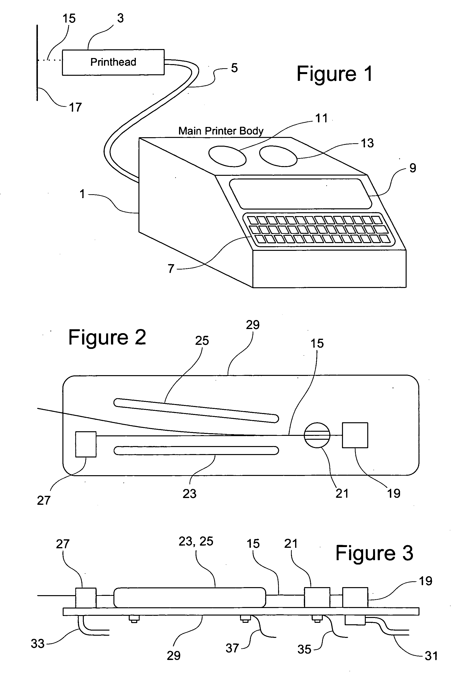
[0052]FIG. 1 shows an ink jet printer. The printer has a main body 1 and a printhead 3, joined by a flexible conduit 5 (sometimes also known as an umbilical).

[0053]The main body 1 has a keypad 7 and a display 9 to enable the operator to communicate with it. The body 1 contains most of the pumps, tanks, valves and control electronics of the printer. Removable filler covers 11, 13 provide access to tanks for ink and solvent (sometimes referred to as diluent), so as to enable the tanks to be refilled.

[0054]The ink jet is formed at the printhead 3, and accordingly the printhead includes the components which must be situated in the vicinity of the jet. The conduit 5, which is typically between 1 and 10 m long, provides a flexible connection carrying the fluid and electrical lines which need to run between the main body 1 and the printhead 3. Although in principle...


PUM


Abstract

An ink/air separator for an ink jet printer has one or more plates 77, 79, 81, 83 over which an ink/air mixture can spread. Preferably there is more than one plate, and the mixture overflows from one plate to the next. Preferably adjacent plates are spaced so that as the mixture passes between two plates it contacts the surface above it as well as the surface below it. The plates may be separated by a gap of 10 mm or less, e.g. a gap of 2 mm to 5 mm, where they overlap Preferably some or all of the plate surfaces contacted by the mixture are roughened. Interaction between the ink/air mixture and the plate surface tends to slow the flow of very small air bubbles and encourage them to accumulate and/or merge, so that they separate from the ink more quickly than individual small bubbles. The ink/air separator may be connected in the path of unused ink returned from the gutter 27 of a continuous ink jet printer to an ink tank 39, or may be placed inside the ink tank 39.

Description

BACKGROUND OF THE INVENTION[0001]The present invention relates to an ink jet printer and an arrangement for promoting the separation of ink and air in an ink jet printer. Aspects of the invention also provide an ink tank for use in an ink jet printer, the ink tank comprising the arrangement for promoting separation of ink and air and optionally also comprising a filter, and a removable module comprising the ink tank.[0002]Continuous ink jet printers are commonly used for printing identification and other variable data on industrial products and packaging. During operation of a continuous ink jet printer, a continuous stream of ink drops is generated and means are provided for deflecting the drops in flight, so that different drops can travel to different destinations. Since the drops are generated continuously, only some of the drops will be required for printing. Accordingly, the drops required for printing are arranged to travel in a direction so that they reach the surface to be ...

Claims


Application Information

Patent Timeline
Patent Type & Authority Applications(United States)
IPC IPC(8): B41J2/19
CPCB41J2/175B41J2/19B41J2/18B41J2/17513
Inventor PLUMMER, MARC
Owner LINX PRINTING TECH
Why Eureka
Try Eureka