Eureka AIR delivers breakthrough ideas for toughest innovation challenges, trusted by R&D personnel around the world.

Back Frame and Backlight System

Active Publication Date: 2013-05-23
TCL CHINA STAR OPTOELECTRONICS TECH CO LTD
View PDF4 Cites 3 Cited by
  • Summary
  • Abstract
  • Description
  • Claims
  • Application Information

AI Technical Summary

Benefits of technology

The present invention provides a back frame and a backlight system that meet requirements at a reduced cost. The system uses at least two primary assembling pieces with different thermally conductive materials to improve strength and facilitate heat dissipation. The back frame is easily fixed to a circuit board, reducing manufacturing costs for flat panel display devices.

Problems solved by technology

The unitary back frame 10 consumes much material and has a high material cost.
Further, a large-sized back frame 10 requires large-sized stamping equipment, and the size of mold corresponding to such a back frame 10 is large and the structure complicated, making the expenditure of the back frame mold high.
As a consequence, the conventional back frame is of a high cost.

Method used


Image

  • Back Frame and Backlight System
  • Back Frame and Backlight System
  • Back Frame and Backlight System

Examples


first embodiment

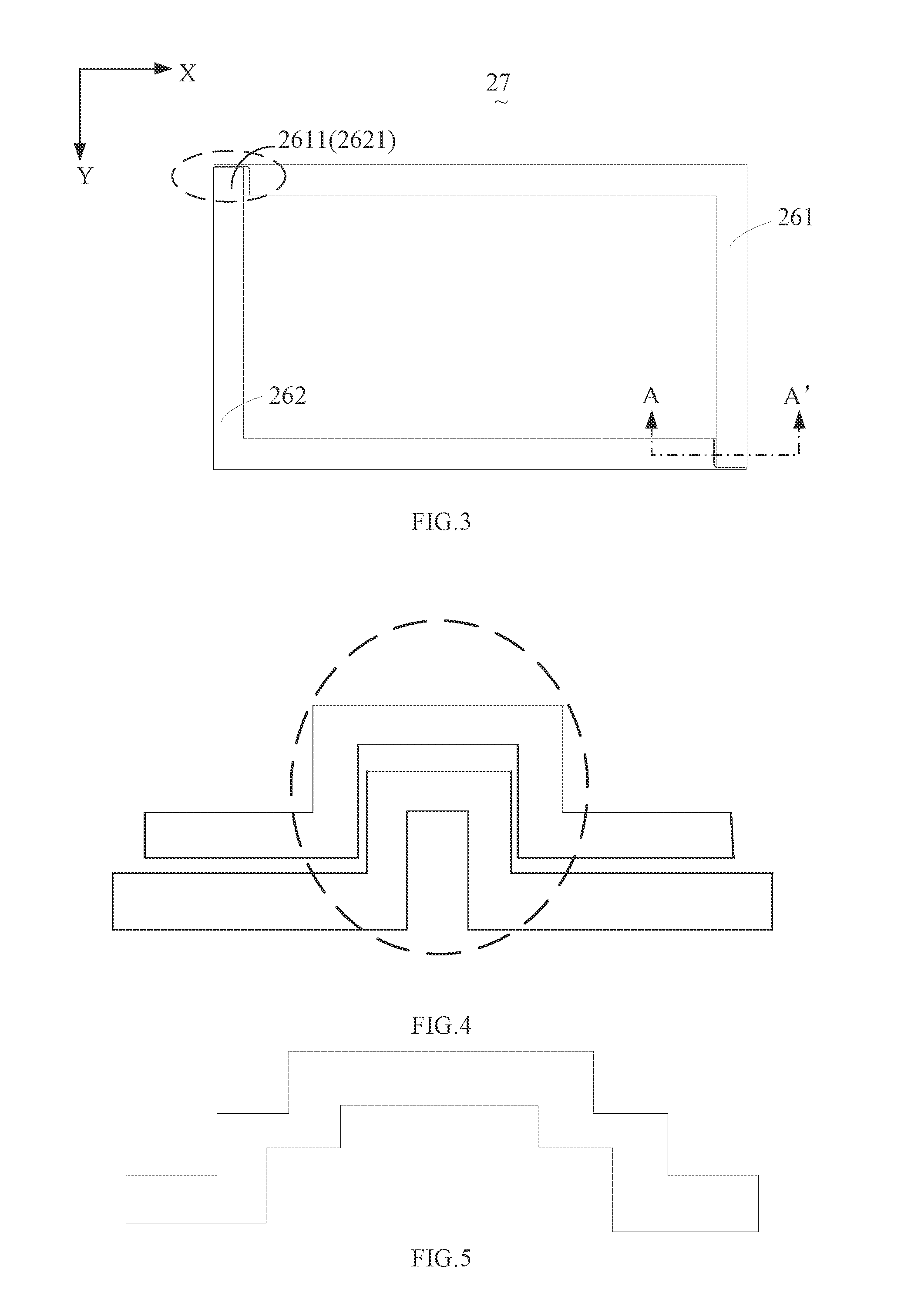
[0073]Referring also to FIG. 3, the back frame 23 of the first embodiment comprises a first primary assembling piece 261 and a second primary assembling piece 262. The first primary assembling piece 261 has an end joined to an end of the second primary assembling piece 262, and the first primary assembling piece 261 has another end joined to another end of the second primary assembling piece 262 in order to form the main frame structure 27 of the back frame 23. The first primary assembling piece 261 and the second primary assembling piece 262 are both aluminum pieces or galvanized steel pieces. In the instant embodiment, the first primary assembling piece 261 and the second primary assembling piece 262 are L-shaped.

[0074]Further referring to FIG. 3, in the instant embodiment, the first primary assembling piece 261 comprises a joint section 2611 and the second primary assembling piece 262 comprises a joint section 2612. At least one of the first primary assembling piece 261 and the s...

second embodiment

[0082]Referring also to FIG. 15, the back frame 23 of a second embodiment comprises a first primary assembling piece 281, a second primary assembling piece 282, and a third primary assembling piece 283. The three primary assembling pieces 281, 282, and 283 are assembled and joined to form a main frame structure 27 of the back frame 23. The three primary assembling pieces 281, 282, and 283 are all aluminum pieces or galvanized steel pieces. In the instant embodiment, the first primary assembling piece 281 is L-shaped, and the second and third primary assembling pieces 282, 283 are straight linear.

[0083]Further, the back frame 23 further comprises secondary assembling pieces arranged inside and joined to the main frame structure 27.

[0084]A detailed description will be given to the back frame 23 of the flat panel display device 20 according to the present invention, which comprises four primary assembling pieces and two secondary assembling pieces.

fourth embodiment

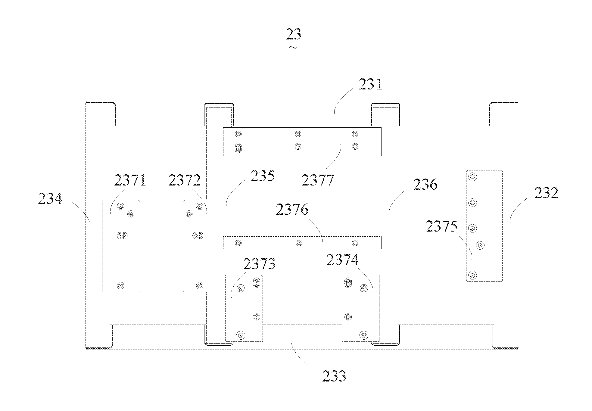
[0085]Referring to FIG. 16, FIG. 16 is a schematic view showing a back frame of flat panel display device according to the present invention. As shown in FIG. 16, in the instant embodiment, a back frame 23 comprises: a first primary assembling piece 231, a second primary assembling piece 232, a third primary assembling piece 233, a fourth primary assembling piece 234, a first secondary assembling piece 235, a second secondary assembling piece 236, and bracing pieces 2371, 2372, 2373, 2374, 2375, 2376, and 2377. The first primary assembling piece 231, the second primary assembling piece 232, the third primary assembling piece 233, and the fourth primary assembling piece 234 are successively joined to each other in an end-to-end manner to constitute a rectangular main frame structure 27 of the back frame 23. The first secondary assembling piece 235 and the second secondary assembling piece 236, serving as ancillary assembling pieces, are arranged in the main frame structure 27 and joi...


PUM


Abstract

The present invention provides a back frame of flat panel display device and a backlight system. The back frame includes primary assembling pieces, secondary assembling pieces, and a bracing piece for fixing a circuit board. The at least two primary assembling pieces are connected through joining and the two primary assembling pieces use different thermally conductive materials. Further, the primary assembling piece includes a joint section that forms a reinforcement structure and a circuit board is mountable and position adjustable through a bracing piece. The present invention also provides a backlight system. The back frame and the backlight system of the present invention have a back frame of simple structure, reduce the expenditure of a back frame mold, facilitate heat dissipation, allow strength of the back frame to meet a desired requirement, improve fixing of circuit board, and save the material used for back frame so as to lower down the manufacturing cost of flat panel display device.

Description

BACKGROUND OF THE INVENTION[0001]1. Field of the Invention[0002]The present invention relates to the field of displaying techniques, and in particular to a back frame of a flat panel display device and a backlight system.[0003]2. The Related Arts[0004]The state-of-the-art liquid crystal display device comprises a front bezel, a panel, and a backlight module, of which the backlight module comprises a back frame, a reflector plate, a light guide, and a lighting assembly.[0005]Currently, a variety of display panels of different sizes are available in the market to meet different needs of general consumers. For example, in the field of television set, the sizes of liquid crystal panels include 31.5, 42, 46, 48, and 55 inches. Different back frame molds are provided for liquid crystal planes of different sizes.[0006]Referring to FIG. 1, FIG. 1 is a schematic view showing a conventional back frame of liquid crystal display device. As shown in FIG. 1, the conventional back frame 10 is a un...

Claims


Application Information

Patent Timeline
IPC IPC(8): G09F13/04H05K7/00
CPCG02B6/0086G02F1/133308G02F2201/46G02F2001/133314G02F2001/133328G02F1/133608G02F1/133314G02F1/133328
Inventor KUO, YI-CHENGHSIAO, YU-CHUNHUANG, CHONGCHENG, JIA-HEQUE, CHENG-WENLI, QUANYANG, LIU-YANG
Owner TCL CHINA STAR OPTOELECTRONICS TECH CO LTD
Why Eureka
Eureka Blog
Learn More