Surge absorber and manufacturing method thereof
a technology of surge absorber and manufacturing method, which is applied in the direction of emergency protective arrangements, emergency protection arrangements for limiting excess voltage/current, and arrangements responsive to excess voltage, etc., can solve the problems of insufficient durability inability to stably use conventional surge absorber at a high voltage, and insufficient joining strength of conventional surge absorber. achieve the effect of improving joining strength and discharge performan
- Summary
- Abstract
- Description
- Claims
- Application Information
AI Technical Summary
Benefits of technology
Problems solved by technology
Method used
Image
Examples
second embodiment
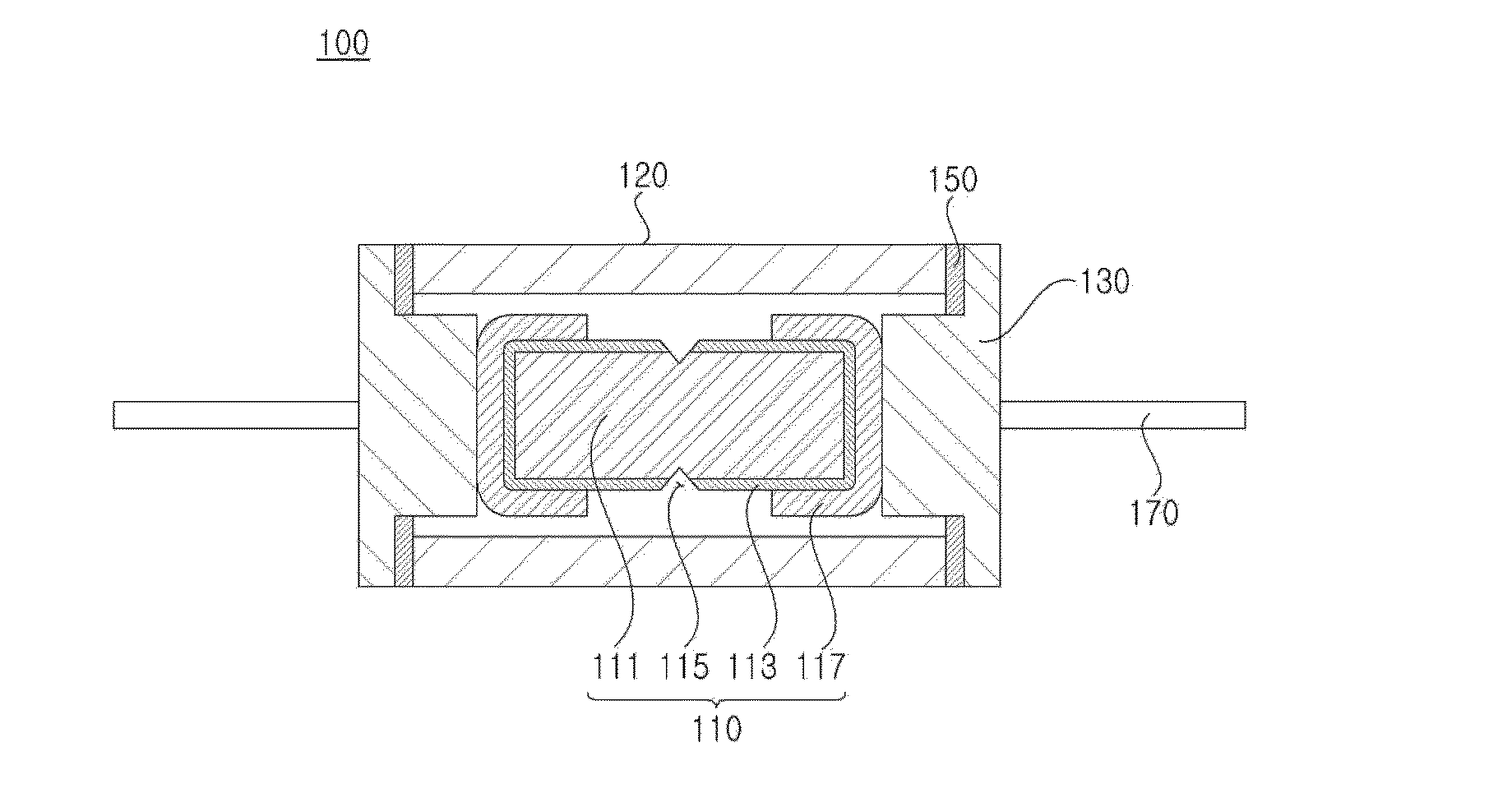
[0055]FIG. 4 is a sectional view illustrating a surge absorber 100a according to the present invention.
[0056]Referring to FIG. 4, the surge absorber 100a according to the present invention may further include brazing members 160 that join each of the contact portions 133 to each of the terminal electrodes 117.
[0057]For example, the brazing member 160 may have a plate shape and may be formed of an alloy including copper (Cu), silver (Ag), and zinc (Zn).
[0058]The brazing member 160 is melted between the contact portion 133 and the terminal electrode 117 to join the contact portion 133 to the terminal electrode 117 in the same manner as the brazing ring 150.
[0059]Thus, the surge absorbing unit 110 may be more firmly joined to the sealing electrodes 130 by use of the brazing members 160, thereby improving durability of the surge absorber 100a.
third embodiment
[0060]FIG. 5 is a sectional view illustrating a surge absorber 100b according to the present invention.
[0061]Referring to FIG. 5, each of the brazing rings 150a of the surge absorber 100b according to the present invention may be configured to be joined to both of the ceramic tube 120 and the surge absorbing unit 110.
[0062]That is, the brazing ring 150a may include an outer portion 153 that is joined to an end of the ceramic tube 120 and an inner portion 154 that is joined to an end portion of the surge absorbing unit 110, particularly, the terminal electrode 117.
[0063]Thus, the brazing ring 150a may have a thickness identical to or greater than that of the contact portion 133a. This is because, when the thickness of the brazing ring 150a is greater than that of the contact portion 133a, the brazing ring 150a may be joined to both the ceramic tube 120 and the terminal electrode 117 after being melted.
[0064]In addition, the inner portion 154 of the brazing ring 150a may be formed to ...
fourth embodiment
[0065]FIG. 6 is a sectional view illustrating a surge absorber 100c according to the present invention.
[0066]Referring to FIG. 6, the surge absorber 100c according to the present invention may further include a plating layer 180 in order to improve wetting properties of the brazing ring 150 or the brazing member 160 with base metals.
[0067]In particular, the plating layer 180 (181, 183, and 185) is formed on at least one of the contact portion 133, the junction portion 131, and the terminal electrode 117 to improve joining strength of the brazing ring 150 or the brazing member 160 and to improve discharge properties by a melting process.
[0068]In addition, the plating layer 180 may include nickel (Ni) or titanium (Ti), and may be formed of, for example, a compound such as Ni3P.
PUM
| Property | Measurement | Unit |
|---|---|---|
| temperature | aaaaa | aaaaa |
| temperature | aaaaa | aaaaa |
| temperature | aaaaa | aaaaa |
Abstract
Description
Claims
Application Information
 - R&D
- Intellectual Property
- Life Sciences
- Materials
- Tech Scout
- Unparalleled Data Quality
- Higher Quality Content
- 60% Fewer Hallucinations
Browse by: Latest US Patents, China's latest patents, Technical Efficacy Thesaurus, Application Domain, Technology Topic, Popular Technical Reports.
© 2025 PatSnap. All rights reserved.Legal|Privacy policy|Modern Slavery Act Transparency Statement|Sitemap|About US| Contact US: help@patsnap.com


