Light-emitting diode lamp

Active Publication Date: 2013-05-23
HUIZHOU LIGHT ENGINE LTD
View PDF18 Cites 42 Cited by
  • Summary
  • Abstract
  • Description
  • Claims
  • Application Information

AI Technical Summary

Problems solved by technology

However, soldering requires relatively complicated processing, performed either by hand or by automation.
However, with such a desi

Method used


Image

  • Light-emitting diode lamp
  • Light-emitting diode lamp
  • Light-emitting diode lamp

Examples


Embodiment Construction

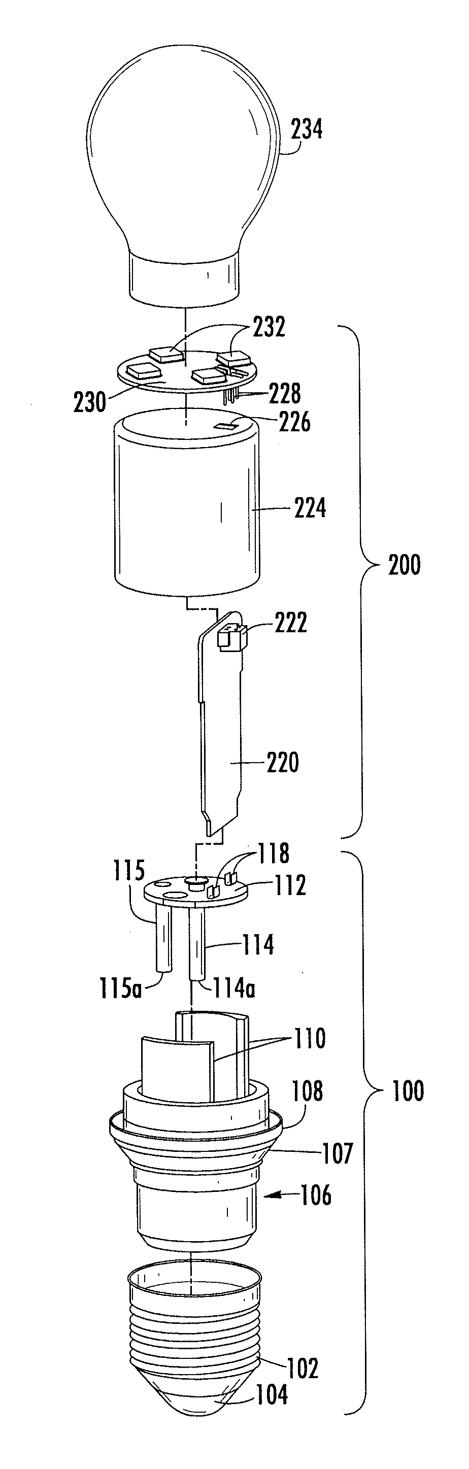
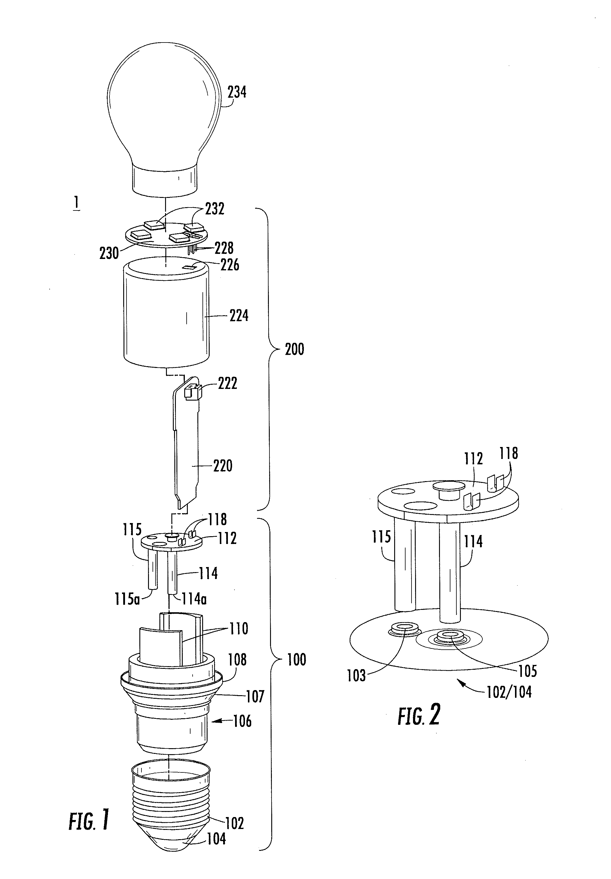
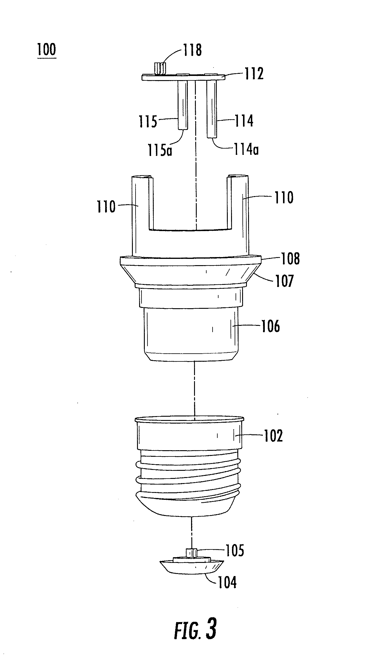
[0037]In order to overcome the difficulties of the prior art, in the embodiments of the present invention an LED lamp holder is provided comprising a secure electrical connection between a source of electrical power and the LEDs, while providing ease of manufacturing of the components and the assembled unit. As discussed in more detail below, the present invention preferably utilizes a spring pin connection design that electrically couples the LEDs with the lamp base and the source of electrical power. According to additional aspects of the present invention, a heat sink is located so that it is within the globe, e.g., within the glass of the bulb, in the assembled LED lamp, allowing heat to be dissipated from the LED device, through the globe to the outside environment, providing a reduction in the amount of exposed metal as compared with conventional LED lamps.

[0038]FIG. 1 is an exploded view of an LED lamp 1. Lamp 1 includes a lower element group 100 and upper element group 200. ...


PUM

PropertyMeasurementUnit
Poweraaaaaaaaaa
Shapeaaaaaaaaaa
Areaaaaaaaaaaa

Abstract

An LED lamp comprises: a lamp base having live and neutral contacts for supplying electrical power to the LED lamp; a substantially hollow lamp holder; a PCB assembly comprising: first and second connection pins; a table portion attached to the top of each of the first and second connection pins; and at least one connecting structure formed at a top surface of the table portion and electrically coupled to the first and second connection pins; an LED PCB comprising at least one LED affixed to a PCB and an LED PCB connector having connector pins electrically coupled to the at least one LED and to the at least one connecting structure of the table portion; and a heat sink being configured to thermally couple to the at least one LED, and a globe having a bottom portion which is thermally coupled to an outer surface of the heat sink.

Description

CROSS-REFERENCE TO RELATED APPLICATIONS[0001]This utility application claims the benefit under 35 U.S.C. §119(e) of U.S. Provisional Patent Application No. 61 / 563,468, filed Nov. 23, 2011, the entirety of which is incorporated herein by reference.BACKGROUND OF THE INVENTION[0002]The present invention generally relates to improved lamp holders for light emitting diode (“LED”) lighting and LED lamps incorporating such lamp holders, and improved heat dissipation methods and structures, and improved methods and structures for coupling LED lamps to sources of power.[0003]In order to provide electric power to the LEDs in an LED lamp, an electrical connection must be provided from the source of electric power, such as a wall or ceiling power source, or battery, to the LEDs themselves, typically via a PC board (PCB) on which the LEDs are mounted. Conventionally, LED lamps include lamp holders that are soldered with wire connections from the base of the LED lamp to the PCB on which the LEDs ...

Claims


Application Information

Patent Timeline
IPC IPC(8): F21V3/00
CPCF21V3/005F21K9/1355F21V23/006F21V23/06Y10T29/4913F21V29/506F21V29/87F21V29/89Y10T29/53174F21Y2101/02F21K9/23F21K9/238F21Y2115/10H05K1/0209H05K3/366H05K2201/066H05K2201/09027H05K2201/10106H05K2201/10189H05K2201/10318
Inventor LEUNG, TEAN SUE-ANNELI, EDDIE PING KUEN
Owner HUIZHOU LIGHT ENGINE LTD
Why Eureka
Try Eureka