
Method for transmitting channel state information in wireless access system

a wireless access system and channel state technology, applied in the field of wireless access systems, can solve the problem of difficult frequency allocation of a wide bandwidth, and achieve the effect of preventing collision between csi

Active Publication Date: 2013-05-23
LG ELECTRONICS INC
View PDF5 Cites 24 Cited by
  • Summary
  • Abstract
  • Description
  • Claims
  • Application Information

AI Technical Summary

Benefits of technology

[0028]The embodiments of the present invention have the following effects.
[0029]First, a single carrier property for a UL transmission signal during UL transmission of a UE can be maintained using the embodiments of the present invention.
[0030]Second, when CSI for one or more serving cells is transmitted through the same subframe, collision between CSI can be prevented by reporting CSI according to defined UE behavior for CSI reporting. Namely, CSI may be dropped according to priority so as to transmit specific CSI alone among plural pieces of CSI, thereby preventing collision between CSI.
[0031]Third, when CSI transmission for a plurality of serving cells is simultaneously demanded through a plurality of PUCCHs in the same subframe, one piece of control information (i.e. CSI) can be transmitted through one PUCCH.
[0032]It will be appreciated by persons skilled in the art that that the effects that can be achieved through the present invention are not limited to what has been particularly described hereinabove and other advantages of the present invention will be more clearly understood from the following detailed description.

Problems solved by technology

However, it is not easy to allocate frequency of a wide bandwidth except in some areas of the world.

Method used


Image

  • Method for transmitting channel state information in wireless access system
  • Method for transmitting channel state information in wireless access system
  • Method for transmitting channel state information in wireless access system

Examples


Embodiment Construction

Technical Problems

[0008]To reduce distortion of a power amplifier during UL transmission of a UE, a single carrier property needs to be maintained with respect to a UL transmission signal. To this end, it is necessary to define a UE behavior for maintaining a single carrier property of a UL transmission signal when a plurality of Physical Uplink Control Channels (PUCCHs) should be transmitted through the same subframe.

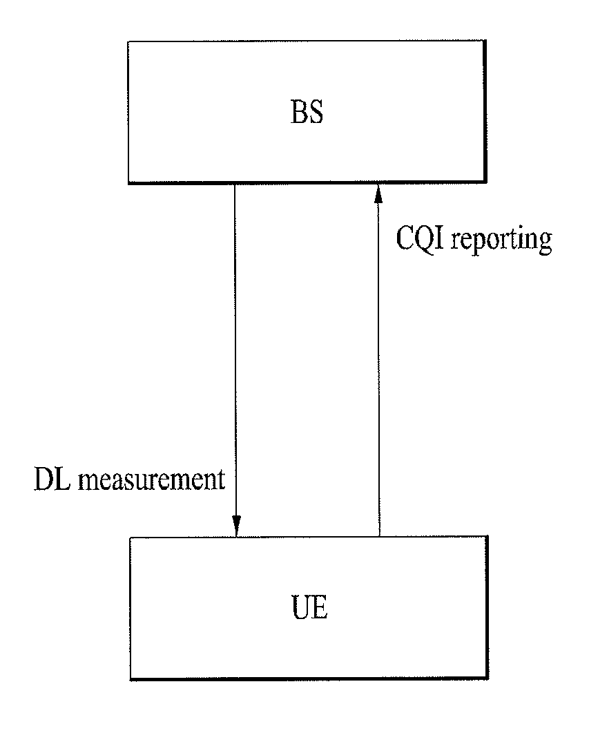
[0009]In one subframe, a UE should transmit control information for one serving cell. If Channel State Information (CSI) for one or more cells is transmitted through the same subframe, a UE behavior for CSI reporting needs to be defined.

[0010]Accordingly, it is an object of the present invention to define a UE behavior in UL for CSI transmission for multiple serving cells in a multicarrier aggregation environment.

[0011]It is another object of the present invention to provide a method capable of transmitting one piece of control information (i.e. CSI) through one PUCCH,...


PUM


Abstract

The present invention provides various methods for transmitting channel state information relative to one or more serving cells in a carrier-coupled environment, and devices for supporting the same. As one embodiment of the present invention, a method for reporting channel state information (CSI) in a wireless access system that supports carrier coupling comprises the steps of: allowing a terminal to receive information related to a CSI report mode for one or more serving cells from a base station; and allowing the terminal to report the channel state information (CSI) on the one or more serving cells to the base station by considering the CSI report mode. In this case, if first type CSI for a first serving cell and second type CSI for a second serving cell are transmitted on the same subframe, the terminal can report CSI for one serving cell only, to the base station, according to priorities of CSI report types related to the CSI report mode.

Description

CROSS REFERENCE TO RELATED APPLICATION[0001]This application is a Continuation of co-pending U.S. application Ser. No. 13 / 638,514 filed on Sep. 28, 2012, which is the National Phase of PCT / KR2011 / 002289 filed on Apr. 1, 2011, which claims priority under 35 U.S.C. §119(e) to U.S. Provisional Application No. 61 / 320,307 filed on Apr. 1, 2010 and to U.S. Provisional Application No. 61 / 389,698 filed on Oct. 4, 2010, all of which are hereby expressly incorporated by reference into the present application.TECHNICAL FIELD[0002]The present invention relates to a wireless access system, and more particularly, to various methods for transmitting channel state information on one or more serving cells in a carrier aggregation environment and apparatuses for supporting the same.BACKGROUND ART[0003]In a general wireless access system, only one carrier is generally considered even though uplink (UL) and downlink (DL) bandwidths are differently configured. For example, a wireless communication syste...

Claims


Application Information

Patent Timeline
Patent Type & Authority Applications(United States)
IPC IPC(8): H04W24/10
CPCH04B7/0626H04L5/001H04W24/10H04L5/0057H04J11/0023H04L1/0026H04J2211/006H04J2211/005H04W72/21H04W72/0453H04L5/0055
Inventor YANG, SUCKCHELKIM, MINGYUAHN, JOONKUISEO, DONGYOUN
Owner LG ELECTRONICS INC
Learn More