Optical engine assembly and optoelectronic package

Inactive Publication Date: 2013-05-23
UNIVERSAL MICROELECTRONICS
View PDF10 Cites 2 Cited by
  • Summary
  • Abstract
  • Description
  • Claims
  • Application Information

AI Technical Summary

Benefits of technology

This patent aims to provide an optical engine assembly and an optoelectronic package that can easily fabricate and achieve high coupling efficiency between the optoelectronic chip and the optical waveguide. The design allows the optoelectronic chip to align with the optical fiber directly, and the shape of the positioning groove allows the optical fiber to be placed close to the chip, significantly increasing the coupling efficiency.

Problems solved by technology

Due to the increase of the transmission capacity, how to improve the light coupling between a plurality of optical fibers and a plurality of laser light sources or photodetectors becomes an importance issue.
In this structure, the front ends of the fibers 932 have to be polished and in some cases a metal layer is coated on the mirror surfaces 932S in order to increase the reflectivity thereof, but these procedures will increase the manufacturing complexity.

Method used


Image

  • Optical engine assembly and optoelectronic package
  • Optical engine assembly and optoelectronic package
  • Optical engine assembly and optoelectronic package

Examples


Embodiment Construction

[0028]It should be noted that, wherever possible, the same reference numbers will be used throughout the drawings to refer to the same or like parts.

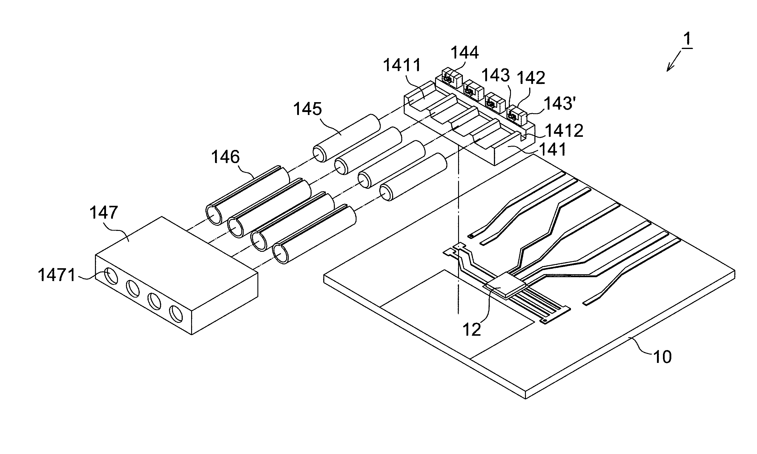
[0029]Please refer to FIGS. 4 and 5, FIG. 4 shows an exploded diagram of the optoelectronic package according to an embodiment of the present disclosure and FIG. 5 shows a schematic diagram of the optoelectronic package according to the embodiment of the present disclosure. The optoelectronic package 1 of the present disclosure includes a substrate 10, a control chip 12 and an optical engine assembly 14.

[0030]The substrate 10 is preferably a PCB substrate and configured to provide the power needed by the control chip 12 and the optical engine assembly 14 during operation. A plurality of conductive lines and through vias are formed on the substrate 10 configured to transmit electric signals, wherein the method of forming conductive lines and through vias on a PCB substrate is well known and thus details thereof will not be repeated herei...


PUM


Abstract

There is provided an optical engine assembly including a bench, at least one optoelectronic unit, at least one optical waveguide and a mount. At least one support groove and a positioning groove are formed on the bench and connected with each other, and the support groove perpendicularly extends outward from one side of the positioning groove. The optoelectronic unit is disposed at the other side of the positioning groove and aligned with the support groove. One end of the optical waveguide is placed inside the support groove and the other end thereof penetrates through at least one through hole of the mount.

Description

CROSS REFERENCE TO RELATED APPLICATION[0001]This application claims the priority benefit of Taiwan Patent Application Serial Number 100142236, filed on Nov. 18, 2011, the full disclosure of which is incorporated herein by reference.BACKGROUND[0002]1. Field of the Disclosure[0003]This disclosure generally relates to an optoelectronic assembly and, more particularly, to an optical engine assembly and an optoelectronic package that do not use conventional light redirecting element to output and / or receive optical signals.[0004]2. Description of the Related Art[0005]Good alignment between an optical fiber and a laser light source or a photodetector can improve the coupling efficiency of light transmission. Due to the increase of the transmission capacity, how to improve the light coupling between a plurality of optical fibers and a plurality of laser light sources or photodetectors becomes an importance issue.[0006]Please refer to FIG. 1, it shows a schematic diagram of a conventional o...

Claims


Application Information

Patent Timeline
IPC IPC(8): G02B6/12
CPCG02B6/428G02B6/421G02B6/4292G02B6/4243G02B6/4249G02B6/423
Inventor LIN, FANG JENGWU, TSU HSIUCHEN, SHIH YUYEH, CHIEN CHUANHUANG, KUANG HUI
Owner UNIVERSAL MICROELECTRONICS
Why Eureka
Try Eureka